Hi everyone, your advice has proven fruitful! I went back and checked (every) resistor and touched up all solder joints (at least the ones I could reach which was nearly all. I now have a working monoblock amp! I don't know if many of you remember the feeling of (finally) hearing music through your first build, but man I'm spinning! Not sure if I'm addicted to building now (or if it's just the effects of excessive solder fumes) but what a rush!
Naturally, for the first signal, I made sure it was the greatest band (at least of my generation). TOOL --> YouTube
It is amp # 2 that is now working, (the one with the unswitched (original) OT wiring).
I think finding the RCA ground (and folding it forward so as to not be making contact with the chassis) was a major find. Glad I went back and touched up the solder joints.
Thanks again everyone for all your help!
Congratulations!
1 down 1 to go, get tired take a break, that's why using a highlighter where you left off is a good tip (hmmm where was I?)- the old timers used crayons.
Haha, yes indeed, taking the night off. It was excruciating to go back and check all the resistor values and I have to admit I was kinda stressed soldering from the top (worried about scorching components). but picked a good tip and went to it. Also terminated the brown, black/green leads properly as was recommended. Glad I did that. Don't want a sticky mess of melted tap in there.
Anyway, fingers crossed for tomorrow to get the other amp going. Have a great night!
 well done.
Trouble in paradise...
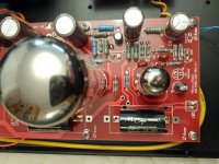
Happy weekend everyone, I was (REALLY) hoping that, since I have one amp working now, that the other would be a snap... not so. Per previous posts, I have switched the A1, A2 wires back to the original setup as per the wiring diagrams, (and as per the first amp which is now working)... I've touched up solder joints from the top but for the life of me I can not see how these amps are different.
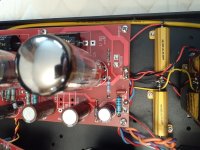
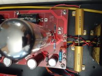
To help us troubleshoot, I've taken lots of pics of the 'good' amp with corresponding pics of the 'bad' amp from as close to the same angle as possible to make things clearer.
Please take a look!
Happy weekend everyone, I was (REALLY) hoping that, since I have one amp working now, that the other would be a snap... not so. Per previous posts, I have switched the A1, A2 wires back to the original setup as per the wiring diagrams, (and as per the first amp which is now working)... I've touched up solder joints from the top but for the life of me I can not see how these amps are different.
To help us troubleshoot, I've taken lots of pics of the 'good' amp with corresponding pics of the 'bad' amp from as close to the same angle as possible to make things clearer.
Please take a look!
Attachments
-
 back of chassis - good.jpg186.9 KB · Views: 121
 -
 top mid driver board - bad.jpg219.4 KB · Views: 51
 -
 top mid driver board - good.jpg205 KB · Views: 56
 -
 top front of driver board - bad.jpg229 KB · Views: 56
 -
 top front of driver board - good.jpg193.8 KB · Views: 55
 -
 bottom of power supply - bad.jpg146 KB · Views: 46
 -
 bottom of power supply - good.jpg187 KB · Views: 114
 -
 top of power supply - bad.jpg189.1 KB · Views: 112
 -
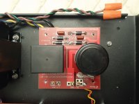 top of power supply - good.jpg165.5 KB · Views: 116
 -
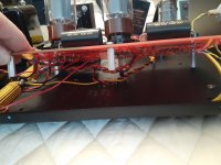
 back of chassis - bad.jpg210.8 KB · Views: 116
continued pics...
Thanks everyone!")
Thanks everyone!
Attachments
-
 Underside driver board - bad - 3.jpg162.3 KB · Views: 39
 -
 Underside driver board - good - 3.jpg194.2 KB · Views: 45
 -
 Underside driver board - bad - 2.jpg178.3 KB · Views: 47
 -
 Underside driver board - good - 2.jpg150.7 KB · Views: 55
 -
 Underside driver board - bad - 1.jpg203.2 KB · Views: 53
 -
 Underside driver board - good - 1.jpg142.6 KB · Views: 56
 -
 top rear driver board - bad.jpg230.4 KB · Views: 41
 -
 top rear driver board - good.jpg234.9 KB · Views: 56
What's it doing?
No power?
Unplug it
Check chassis ground.
Grounding lug connection in Painted Chassis
Does the power outlet connector have a fuse in it? (not according to the schematic)
Check the fuses
No power?
Unplug it
Check chassis ground.
Grounding lug connection in Painted Chassis
Does the power outlet connector have a fuse in it? (not according to the schematic)
Check the fuses
Last edited:
What's it doing?
No power?
Unplug it
Check chassis ground.
Grounding lug connection in Painted Chassis
Does the power outlet connector have a fuse in it? (not according to the schematic)
Check the fuses
Hi Chris, sorry I should have mentioned. It's basically same issue as last time.
* turn power on (with signal already going through it)
* no sound initially, amp is quiet. tubes lit, pwr light on.
* 10-15 secs later - hum comes in, and keeps getting louder (I think it's a lower frequency hum like a 60Hz hum) that gets quite loud till I turn it off
* then high frequency squeal like sound (this time it sounds more like a squeal as opposed to a whistle-like sound; perhaps something like a 1950's radio operator trying to dial in a frequency)... until the caps dissipate 5-10secs later. --> This time also, I'm only getting extremely faint audio signal coming through after powering off... till caps discharge.
to reply to each of your questions:
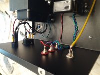
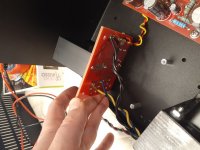
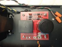
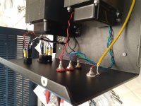
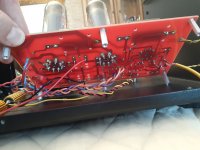
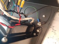
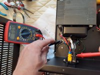
I've got the ground wires here, see pic. (both rocker switch and mains transformer ground going to same lug in the chassis near back left corner of mains tx... I even dremeled the chassis around the lug to ensure better contact. Thx for advice though, I'll dremel it again for good measure.
Yes there is a fuze in the outlet but given what I'm experiencing above, I don't think this would be the issue. I definitely have power going through the amp. (pwr light comes on and tubes light up).
Possible to have a defective OT? - how many times can you solder and desolder the same pad on a board before things start to get ummm... questionable?
Attachments
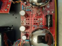
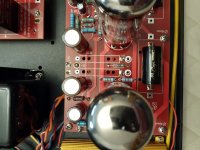
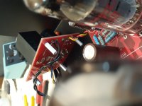
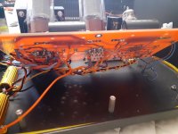
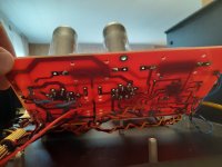
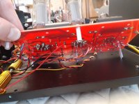
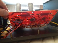
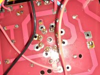
Hi Chris, really appreciate your input. I took a good look around the pins and (to my horror) thought you may have a good point with crossed solder on the pins. --> Horror; as that would be a monumental fix.
I was able to stuff my phone in there and take this pic. Thankfully, it appears I didn't cross any solder across pins.
In trying to think through this logically, (can't remember if I mentioned this or not) but I had built both amps side-by-side, step-by-step.... not one after the other. Thus, any error made on the first amp would be bound to be repeated on the second. This stands to reason as both amps (were) exhibiting the exact same problem upon power up. In order to get the 2nd amp working, I didn't change any wiring or anything like that... I simply took your advice to go over all solder joints, terminate some wires properly, and folded the RCA input ground forward ~30degrees and voila.
I've had a quick (text) chat with Brian at ANK, I was also able to email him a recording of the sound that is being made and he believes it's most likely a grounding issue near the mains terminal. I've measured only 0.5ohm resistence of the ground wire (between rocker switch and ground lug). Does that sound about right to you?
Attachments
2 working monoblock amps!!
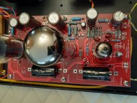
Hi Chris, just wanted to thank you again for your diagnostic advice and to let you all know I've found the problem.... and now have 2 working monoblock amps.
The issue??? not enough solder on the RCA-to-pcb connection! completed now... very happy!
Next step, the ANK L2 preamp.
the bad amp board post#46 picture 4, left power tube the picture looks like there might be some solder across 2 pins on the right.
You could run wood or plastic stick around the bottom/ socket pins.
Hi Chris, just wanted to thank you again for your diagnostic advice and to let you all know I've found the problem.... and now have 2 working monoblock amps.
The issue??? not enough solder on the RCA-to-pcb connection! completed now... very happy!
Next step, the ANK L2 preamp.
- Status
- This old topic is closed. If you want to reopen this topic, contact a moderator using the "Report Post" button.
- Home
- Amplifiers
- Tubes / Valves
- EL34 monoblock kit build... troubleshoot