I really want to finish my BH EL84 build but am struggling to find a decent layout that I like.
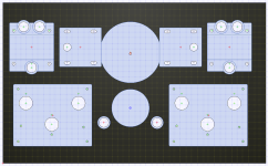
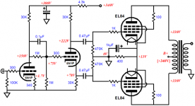
The one attached is with an Antek toroidal PT with 2x250V and 2x6.3V. In this layout each board would get its own 250V and 6.3V supply.
The small transformer is a 2x30VAC wired in series for bias supply... but I think 60VAC is a bit high here (posted about this a bit earlier).
Also, if that single transformer is used for both boards, isn't it problematic to use a single transformer for 2 different rectifier circuits (each board has its own voltage doubler for the bias)? It seems like a 2x48V transformer would be better (one tap for each board).. but can't really find anything suitable.
The top transformers are a OPT and Hammond 193 enclosed chokes.
I thought about converting to monoblocks but it seems way overkill.
I'm looking for ways to simplify this. One option is to the PSU (bridge + 2 caps) of a single board, with an HV regulator and connect the regulator in parallel to both boards. This would allow me to get rid of both the chokes and only require a single HT tap. I could use something like the Edcor XPWR262-120 (250V@300mA, 6.3VCT@6A). I would still require a bias transformer though.
Attachments
Hi @itsikhefez
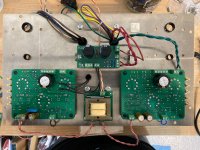
I used a similar Antek toroid, only used a single choke and used the same HV to both boards, I also used the external psu board and thus used the 6.3V DC Buck booster for the heaters
I used a 30-0-30 for the bias - used 30-0 for one board and 0-30 for the other , 30V AC is plenty to achieve the necessary bias voltages with the onboard
This is how I ended up laying it out


the underside ( there is a slight error in wiring for those with sharp eyes but it was corrected before any catastrophe )

..dB
I used a similar Antek toroid, only used a single choke and used the same HV to both boards, I also used the external psu board and thus used the 6.3V DC Buck booster for the heaters
I used a 30-0-30 for the bias - used 30-0 for one board and 0-30 for the other , 30V AC is plenty to achieve the necessary bias voltages with the onboard
This is how I ended up laying it out
the underside ( there is a slight error in wiring for those with sharp eyes but it was corrected before any catastrophe )
..dB
thank you . it is 17.5 x 12
it was scrap left over from a recycled enclosure that I cut down to fit the build. It was pretty beat up but I knew that stainless can be made to look reasonable with a little sanding - I gave up on the idea of mirror polish when my arm was aching and I had only achieved a small patch to the high sheen I was originally aiming for")
The little switches - activate small voltage meters for the EL84 bias , I set the meters using my DMM , so they are accurate enough for me to check/adjust the bias without any major effort.
it was scrap left over from a recycled enclosure that I cut down to fit the build. It was pretty beat up but I knew that stainless can be made to look reasonable with a little sanding - I gave up on the idea of mirror polish when my arm was aching and I had only achieved a small patch to the high sheen I was originally aiming for
The little switches - activate small voltage meters for the EL84 bias , I set the meters using my DMM , so they are accurate enough for me to check/adjust the bias without any major effort.
R15 ensures a more gradual charging of the power supply capacitors before the relay closes, which allows for switching of a lower voltage differential across the relay and reduces the current surge when the relay closes. I believe R15 helps the specified relay to survive this application better and provides a “smoother start”.
Last edited:
Frankly, I doubt it because when the cathodes become hot, the HV will collapses to a low value up to the contact is on and we’re back at the beginning ! More, cathode stripping is there... Best think to do IMHO is to displace the contact after the second filtering capacitor.
The purpose of R15 is to gently charge C3 and C10 up to when the 555 switches the relay.
In 5RC (approximately 22 second) the cap will be totally on, whilst the time for each power tube to start working change tube by tube. The relay must switch before the tubes will start conducting, but not too much earlier in order to have charged the capacitors to a good value.
Some tubes may require to lower R15 in order to charge the capacitors and switch before they'll start conducting.
François, the issue (on the long terme) is the phenomene named "cathode stripping". Cathodes dont like to delivers electrons when they are not at the good temperature. This change the beavior of the cathode, introduce a parasite resistor in it among others That's why, it could have been a better idea to put the contact of the relai after the 470uF and not before as you can see the 47uF. By the way, in such configuration, the 10 Ohm thermistance is useless because is value is at least one order un ordre of magnitude lower that the transformator resistance aniway.
Zintolo, for sure a power tube conduct well before 22secondes. At this moment, the voltage accross the 470uf capacitor slide down generating cathode striping and then when the contact close, over current on the transformator. Yes, we have to adjust the LM555 time constante to be placed in the ideal situation you describe. That's why I am not completly convinced by this passing trick. In such a way, we will have to change te relais before the tubes !
Zintolo, for sure a power tube conduct well before 22secondes. At this moment, the voltage accross the 470uf capacitor slide down generating cathode striping and then when the contact close, over current on the transformator. Yes, we have to adjust the LM555 time constante to be placed in the ideal situation you describe. That's why I am not completly convinced by this passing trick. In such a way, we will have to change te relais before the tubes !
Hi @itsikhefez
I used a similar Antek toroid, only used a single choke and used the same HV to both boards, I also used the external psu board and thus used the 6.3V DC Buck booster for the heaters
I used a 30-0-30 for the bias - used 30-0 for one board and 0-30 for the other , 30V AC is plenty to achieve the necessary bias voltages with the onboard
This is how I ended up laying it out
the underside ( there is a slight error in wiring for those with sharp eyes but it was corrected before any catastrophe )
..dB
Thanks for the information. I finally had some time to work on this and went with a similar approach.
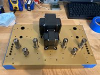
I used a Hammond 370HX (550VCT) which I already had on the shelf. I used a small PCB for a CLC PSU that mounts directly underneath it. The board uses 2 diodes in a FWCT configuration with R-C snubbers.
That B+ voltages is wired to the PSU resistor on the PCB's for another RC stage on each board. (not pictured)
The choke I used is a Hammond 193H, 5H with 65 ohms resistance. With the high mains voltage in my home (~124VAC), I needed a 300R resistor on each board.
Since the Hammond has a 5VAC winding, I may consider using a tube rectifier to drop some voltage that way.
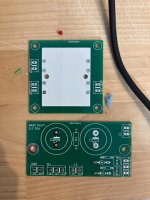
For the bias, I wasn't entirely happy with the dual 30VAC toroids. While they may be sufficient for bias, I wasn't sure if that provides sufficient voltage for the drivers (which need 50V+ to my understanding).
Anyhow, I found this small 12VA transformer with dual 50VAC windings. It is PCB mounted so I made a small PCB for it.
I have more PCB's if anyone wants to take this route too.
Attachments
Thanks for the information. I finally had some time to work on this and went with a similar approach.
I used a Hammond 370HX (550VCT) which I already had on the shelf. I used a small PCB for a CLC PSU that mounts directly underneath it. The board uses 2 diodes in a FWCT configuration with R-C snubbers.
That B+ voltages is wired to the PSU resistor on the PCB's for another RC stage on each board. (not pictured)
The choke I used is a Hammond 193H, 5H with 65 ohms resistance. With the high mains voltage in my home (~124VAC), I needed a 300R resistor on each board.
Since the Hammond has a 5VAC winding, I may consider using a tube rectifier to drop some voltage that way.
For the bias, I wasn't entirely happy with the dual 30VAC toroids. While they may be sufficient for bias, I wasn't sure if that provides sufficient voltage for the drivers (which need 50V+ to my understanding).
Anyhow, I found this small 12VA transformer with dual 50VAC windings. It is PCB mounted so I made a small PCB for it.
I have more PCB's if anyone wants to take this route too.
Looks good. There are a lot of modules to put in place to get one of these BH amps up and running. FYI you do not need +50 for the driver voltage. +20 will be enough. We do not need or want to drive the power tube grids positive so the mosfet only needs about +10v to stay linear with a 0 volt output. I think my BH el34 ended up at +22. You do need at least 2.5 x your -bias voltage setting on the negative side to make sure the power tubes will be driven all the way to cutoff. So, if you are running -30v bias on el34s you want at least -75v. For an EL84 version you are typically running -10 or so on the grid, so at least -30v should do the job.
Last edited:
Thanks for the info.
With the dual 30VAC toroid I had max -18V on the EL84 grid, and 25V on the driver.
Now there is up to -40V on the EL84 grid, and +55V on the driver, so seems better.
I like using the PCB as it opens up the possibility to use transformers with a center-tapped HT.
Still contemplating a tube rectifier to drop some of that voltage down.
The choke I used is a Hammond 193H ...
I was under the impression it was a good idea to try and orientate the choke in a different plane to the power transformer to minimise coupling, and ideally the OPTs too. I presume it has worked OK for you to have them aligned?
Thanks dB.
OldHector, yes, generally you are right.
The OPTs will be at a right angle to the PT.
The choke then can either be in the same plane as the OPT or the PT... I chose PT.
I haven't tested it entirely yet, just initially voltages. I'll report back if any issues, worst case I can rotate it.
OldHector, yes, generally you are right.
The OPTs will be at a right angle to the PT.
The choke then can either be in the same plane as the OPT or the PT... I chose PT.
I haven't tested it entirely yet, just initially voltages. I'll report back if any issues, worst case I can rotate it.
Trying to figure out a hum issue with my BH build...
With the inputs shorted, the amp is dead quiet.
When connected to a source (DAC with volume control), there is audible hum.
The interesting part is that if only one channel is connected , the amp is still dead quiet.
I suspect some sort of grounding issue between the dual boards and the power supply (I am using a single shared power supply PCB).
Can anyone suggest the proper way to connect the PCB's ground to the common PSU and how to tie back to the chassis?
I know you posted this last year - but were you comparing this to the schematic from Tubecad attached here? Do you still think the BH was better than the Broskie design? I have to redo mine, and I always thought it sounded great.... but of course if there is something else out there better then I'm all ears!!Yes. There is some temporary board that I'm using since I'm planning a 21st century Maida regulator. So disregard that.
That is the on-off switch. And you are correct that I have a self-made adapter to measure bias with a multimeter. Picture soon.
I'll do that once the regulator has been installed because the temp board has too high a voltage and I can't be bothered to lower it.
Ofcourse. Did some early comparison between this BH...and my son's Broskie with 6p1p. No contest. BH is in a league above. But not a like for like comparison ofcourse. Because of different output transformers, tubes and coupling caps. I have already altered my Broskie el84 version to a podwatt type...that should tell you something already. Because the Broskie was fine for Mission 753 in my kids room. But just not good enough of my main speakers.
Attachments
- Home
- Amplifiers
- Tubes / Valves
- Oh no...not another Baby Huey EL84 build.