So, working this out in my mind, in a DH tube with a DC filament supply, the effective cathode voltage is the voltage of the most positive side of the filament supply. Old datasheets say as much, and it makes intuitive sense.
Let's say we have a terrible-quality (say 1V pk-pk ripple, for the sake of argument) floating DC filament supply and we connect the positive side to a good quality ground and let the negative side sit at a negative voltage with all the ripple on it. The tube is biased with a perfectly clean bias source and input is muted.
How much of that 1V ripple will appear at the anode? None? A tiny bit? What's the typical negative-side filament supply rejection ratio of a DH tube?
Does anyone know of any measurements of this on the net anywhere?
I'm somewhat puzzled, as there's a convention with DC heated DH tubes that any electrode voltage relates to the filament's negative end, not to the positive one. This makes sense, as at the negative end you always measure a current that is larger by the sum of plate and screen current (if given) than the current at the positive end. In other words: The negative end supplies all the electrodes' current, regardless where the filament is grounded.So, working this out in my mind, in a DH tube with a DC filament supply, the effective cathode voltage is the voltage of the most positive side of the filament supply. Old datasheets say as much, and it makes intuitive sense.
Best regards!
> How much of that 1V ripple will appear at the anode?
An unbalanced signal on the filament will be amplified, not rejected. The effective Vgk signal can come from the cathode, too.
Think about circuits for ac-heating: a centre-tap is created: in the ac trafo winding, or a fake CT using a pair of resistors. In each case, it is an attempt to balance the ac-waveform's effect on the triode-curves - either side of the operating point.
But the triode curves are not truly symmetrical, so the results usually disappoint for hum, and intermodulation distortion is non-negligible.
Last edited:
I've always thought it was more an average or mid-point.
If that's the case, AC heating would create no hum if you referenced to the center tap, right? The positive side of the filament would always be going up by the same amount that the negative side is going down.
But that's clearly not the case, since AC heating makes hum.
You'd have to simulate the electric field and space charge around the filament in geometric detail to answer the question, or just measure it.
<Sigh>, I was hoping that someone else had already measured it so that so I wouldn't have to.
An unbalanced signal on the filament will be amplified, not rejected.
Unbalanced with respect to what?
When we AC heat and tie the center tap to GND (fixed bias applied to grid), do we see a sine wave on the anode, or do we see what looks like half-wave rectified humps impressed on the anode signal?
I'm somewhat puzzled, as there's a convention with DC heated DH tubes that any electrode voltage relates to the filament's negative end, not to the positive one.
Do you have a reference that shows an example of this? I swear I can remember looking at a tube datasheet that stated the opposite, but I can't seem to find it right now.
I can settle this definitively with a little testing in the garage. I've got 841s running at -2.5V bias on a 7.5V filament. It should be easy to determine what matches the tube data. My memory tells me that the most positive side was the correct reference that the curves were drawn to, but my memory isn't always 100% reliable.
Last edited:
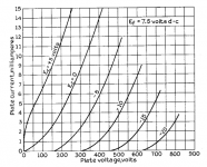
So...I made some measurements. I have attached the 841 curves, which specify DC on the filaments. From my measurements and the curves, we can deduce whether the effective cathode voltage of a directly-heated tube is the most positive side, the most negative side, or some point in between.
I run my 841s at 10mA with a CCS plate load, biased for 400V on the plate. I read a little less than -2.5V grid bias required for my operating point.
I connected the meter common to the grid and probed both sides of the filament and got 2.35V and 9.77V.
Looks like Kay Pirinha is correct (and I was wrong), and the negative side of the filament is the reference for drawing the curves.
The basic question I am after in all of this, though, still stands. I'm trying to determine which is the best side of the filament to connect to the low-impedance reference point in the circuit. Since all DC supplies are imperfect to some degree, which way will be more forgiving of the filament supply imperfections? Or are they both the same? That seems less likely to me but my intuition has steered me wrong before.
Attachments
All of these assumptions are based on the emission being constant along the entire length of the filament, and that the build quality is perfect such that the spacing between the filament, grid and plate also remain constant throughout the active area.
All real world tubes are different, and no perfect heater supply exists. What results in a near perfect hum cancellation with one tube will not be quiet with the next. Measurements on several similar tubes reflect this, and some tubes, particularly early Sovtek 300B's just can not be adjusted to inaudible levels.
I spent a good deal of time testing several different heating schemes with DHT's about 15 years ago. All have their advantages and disadvantages. The hum level can indeed be nulled down to "quiet" levels in a typical AC heating scheme, but as stated the non-negligible IMD created adds to listener fatigue.
A good symmetrical sine wave at around 100 KHz with its CT grounded performed the best in testing and listening, as the residual hum and IMD artifacts are all well above the audio band and should not make it through the OPT. It was a rather complicated design 15 years ago, so the Tubelab TSE went with pure DC.
You can build a DC supply with microvolt levels of ripple such that hum and heater related IMD are not an issue, even with headphones connected directly across the speaker terminals.
There is still the debate as to whether constant voltage or constant current DC is "best." Ask yourself how much it matters when the filament has a DCR of 1 ohm or so (2A3).
So, George, which end do you connect to GND when you build an amp with a DC filament supply, and does it make a real difference?
I'm using Tom Christiansen's switching supplies (a fairly quiet 500kHz switcher) and just want to choose the theoretically best way, but I'm not sure defects will be measurable either way I connect it.
I'm using Tom Christiansen's switching supplies (a fairly quiet 500kHz switcher) and just want to choose the theoretically best way, but I'm not sure defects will be measurable either way I connect it.
If that's the case, AC heating would create no hum if you referenced to the center tap, right? The positive side of the filament would always be going up by the same amount that the negative side is going down.
But that's clearly not the case, since AC heating makes hum.
AC heating cannot have zero hum because the triode curves are not perfectly symmetrical about the operating point. So the cancellation only works imperfectly. Even when the hum is nulled to the best extent with a hum-pot, this mechanism generates 2nd harmonic, in the usual way, and forms the audible hum - 100Hz for 50Hz mains.
If you 'reference' the ac-heated 'cathode' to anything other than a centre-tap of the trafo, or a faked CT made with low-value resistors, the hum from ac-heat will be of speaker-crunching proportions. The hum-pot helps, because it allows the best cancellation for the actual curves of the DHT in the circuit.
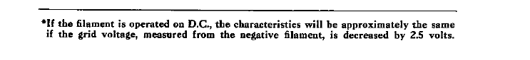
About data-sheet definitions of 'reference': the centre-position is assumed, for the purposes of setting the nominal grid-voltage. See attached note, from Western Electric DS for 300B pp2 (1950 year).
Attachments
AC heating cannot have zero hum because the triode curves are not perfectly symmetrical about the operating point. So the cancellation only works imperfectly. Even when the hum is nulled to the best extent with a hum-pot, this mechanism generates 2nd harmonic, in the usual way, and forms the audible hum - 100Hz for 50Hz mains.
If you 'reference' the ac-heated 'cathode' to anything other than a centre-tap of the trafo, or a faked CT made with low-value resistors, the hum from ac-heat will be of speaker-crunching proportions. The hum-pot helps, because it allows the best cancellation for the actual curves of the DHT in the circuit.
About data-sheet definitions of 'reference': the centre-position is assumed, for the purposes of setting the nominal grid-voltage. See attached note, from Western Electric DS for 300B pp2 (1950 year).
So, I can't make sense of one thing. If everything you are saying is true, why is there a bias shift with DC heating? It seems to me that we should be able to freeze time in any instant AC heating and analyze it as if it were DC.
Say we've got a fixed-bias 300B and we freeze time when the filamant has 5V across it. One side is at +2.5V and the other -2.5V because center tap is at 0V. How can this give the same operating point as a 300B with 5VDC supply with negative side grounded? What am I missing here? Does it make sense what I'm confused about?
I always assumed that AC heating would couple speaker-crunching hum directly into the grid because I guess I still can't wrap my head around the idea that the AC wouldn't just be a large direct signal injection into the grid circuit. It sounds like you are saying that's not the case normally with a CT. Hmmm, I'm more confused than ever. Having an electrode with a voltage gradient really makes it more complicated.
Last edited:
Say we've got a fixed-bias 300B and we freeze time when the filamant has 5V across it. One side is at +2.5V and the other -2.5V because center tap is at 0V. How can this give the same operating point as a 300B with 5VDC supply with negative side grounded?.
The bias will be shifted by 2.5V if the negative side is grounded (compared to 0V at the CT), so the anode current will not be the same.
To achieve that, we have to shift the grid bias nearer ground by 2.5V, as the WE note indicates...
BTW, I think you may enjoy the work of Dmitri Nizhegorodov - many years ago he investigated & measured the nature of the ac-heated DHT hum-signal, including for different frequencies and waveforms. Maybe his articles will help resolve some of your thoughts.
Part I starts here - be sure to follow on to Part II !
On Correlation Between Residual DHT Filament Hum and AC Frequency
Part I starts here - be sure to follow on to Part II !
On Correlation Between Residual DHT Filament Hum and AC Frequency
The bias will be shifted by 2.5V if the negative side is grounded (compared to 0V at the CT), so the anode current will not be the same.
To achieve that, we have to shift the grid bias nearer ground by 2.5V, as the WE note indicates...
Okay, so any curves drawn with AC heating need to be shifted by 1/2 of the filament voltage to be valid for DC heating.
Thanks for the recommended reading. I have very little experience with directly-heated tubes. I've only used them in one design.
I still would like to know if there is a "better" side to connect to GND on a DC supply, and especially if there is someone who has published measurements showing which way is best or that there is no difference. I'm starting to suspect that there may be no difference now.
Thanks!
So I'm starting to think of the filament as an infinite series of points, each of which has its own voltage relationships to the other electrodes. All of these points working together create the characteristic curves in the datasheet.
Thinking about things this way makes everything make more sense.
The way my regulators work (buck converters) makes connecting the negative side to GND much easier than the other way around. I'd have to have four separate raw DC supplies the other way.
I bought some inductors to see about making a second stage external passive filter to see how clean I can make the DC supply.
- Status
- This old topic is closed. If you want to reopen this topic, contact a moderator using the "Report Post" button.
- Home
- Amplifiers
- Tubes / Valves
- DH DC filament supply to anode coupling