Since your +115 -115V ground is floating, I think a bleeder resistor from + to compensate the bias current from the - is needed.Without it the bias current goes trough the speaker.
Mona
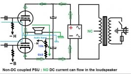
Well no, @Ketje : because the 6080 supply ground is floating, no DC current would flow through the speaker, hence shown in my upper schematic below, no matter the possible imbalance of the supply (on which I put 2 bleeder R to compensate possible starting imbalance while 6080 heating, and mainly to discharge the 1000µ caps).
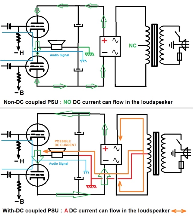
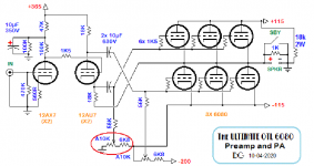
If you look at my amp schematic, you can see that the upper 6080 bias current is returned to GND directly, not via the speaker.
That said, you are partially right : in that amp circuit, there is effectively a little DC current flowing in the speaker permanently : I let you guess where does it comes...
")
A+!
Last edited:
Hi,
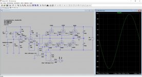
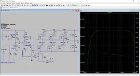
I sent some time trying to modeling your OTL.
The result is quite good.
I got 12.6 Watt peak before clipping @ 1K 0.8V into a 8R resistor.
I too see a idling current of -4.52 mA through the LOAD with no AC voltage in.
I don't know if this is my model or is the same in the real world, but I think it is worth checking.
Now I can do more sim with square signal, FTT and THD. Of course all simulated and not exactly as reality. But my experience is these are pretty accurate...but not always, mostly due to the OT imperfect model.
I hope it helps.
Brice.
Attachments
That said, you are partially right : in that amp circuit, there is effectively a little DC current flowing in the speaker permanently : I let you guess where does it comes...
MonaAttachments
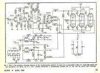
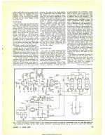
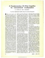
One of the original articles covering this cct is at-
https://www.americanradiohistory.com/Archive-All-Audio/Archive-Audio/50s/Audio-1954-Jun.pdf
Beginning on p22.
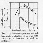
I built a copy of this on an experimental chassis around 1956. It drove a 16Z speaker OK. But the operating conditions for the 6080s result in two serious problems. First of all the resulting loadlines on the tubes are almost vertical, so puts them into a high distortion region. In this cct 40 db NFB helps a lot.
The other problem has to do with fixed bias operation. Low mu triodes are unstable on fixed bias, plate current runaway often occurs. I've seen that first hand as the control grid of one of my tubes disintegrated.
Tube life in OTLs is short at best. IMO, the cct topology creates more problems than it fixes.
https://www.americanradiohistory.com/Archive-All-Audio/Archive-Audio/50s/Audio-1954-Jun.pdf
Beginning on p22.
I built a copy of this on an experimental chassis around 1956. It drove a 16Z speaker OK. But the operating conditions for the 6080s result in two serious problems. First of all the resulting loadlines on the tubes are almost vertical, so puts them into a high distortion region. In this cct 40 db NFB helps a lot.
The other problem has to do with fixed bias operation. Low mu triodes are unstable on fixed bias, plate current runaway often occurs. I've seen that first hand as the control grid of one of my tubes disintegrated.
Tube life in OTLs is short at best. IMO, the cct topology creates more problems than it fixes.
Attachments

Ah, yes : I see now, Ketje - Thanks !
Since I have 2 12K/11W discharge resistors accross each half supply, I didn't thought about the current drawn by that divider which is effectively unilateral. And yes, it represents circa 6mA...
Add to this the current coming from the cathode of the phase splitter, which is in the same sense...
Avoiding the current of the bias divider can be done by returning it to the cathode common point of the 6080s instead of GND - It must be validated though - but for the phase splitter current - inherent to the design - it's another story.
OK - I'll have to dig it...
Well, that's a limited current, but it's not zero, that's true !A+!
From the 12AU7
Yes, that's it. Plus the divider current mentioned by @Ketje now, that I did not saw...
A+!
One of the original articles covering this cct is at-
https://www.americanradiohistory.com/Archive-All-Audio/Archive-Audio/50s/Audio-1954-Jun.pdf
Beginning on p22.
I built a copy of this on an experimental chassis around 1956. It drove a 16Z speaker OK. But the operating conditions for the 6080s result in two serious problems. First of all the resulting loadlines on the tubes are almost vertical, so puts them into a high distortion region. In this cct 40 db NFB helps a lot.
The other problem has to do with fixed bias operation. Low mu triodes are unstable on fixed bias, plate current runaway often occurs. I've seen that first hand as the control grid of one of my tubes disintegrated.
Tube life in OTLs is short at best. IMO, the cct topology creates more problems than it fixes.
My web connection is so poor this evening so I can't even open your files @hstewart9... Don't think about uploading anything !

I'll be back later when the web will be able to work properly.
A+!
Looks like the web in general is overloaded with many folks staying at home. Best time here for me is about 4AM. Our connexion is by Satellite, far from COVID but still a problem!!
Sure
! My connection is a lagging ADSL 512K and it's impossible to obtain the optical fiber here... 
The web situation seems better now at 23:00 local time

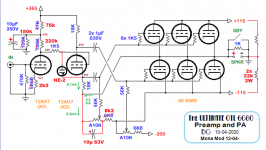
Ah, yes : this is the Dickie-Macovski OTL circuit. I knew this circuit but never found the litterature about it, so thanks, @jhstewart9
Yes, my 1993 OTL amps were similar in design, but with a more simple circuit (based on a Marantz 8B driver idea) with switchable 6dB FB. I had 20WRMS continuous at 3%THD and an output impedance at circa 20R with 4x6080 at the output stage :
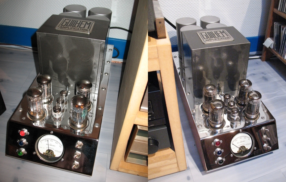
These mono block pair is now sold for years to an enthusiast and he never told me he had issue with it... So it's possible to built reliable OTL circuits !
The Futterman I'm experimenting here is a much more simpler and is set up to a reasonable working point for 10W RMS continuous output (idle current is 300mA, max current at 12.5WRMS continuous onset of clipping reaches 500mA)
A+!
With 2 x 12K across the big caps, I get a resting current of 6.155 mA on the model.
Pretty accurate
Yes @Brice : sorry, I skipped your simulation work...

It's very interesting... Let me know if you want more data so we could compare simulation and reality
The 4.52mA current in the load comes from the Cathodyne phase splitter. I measure 6.1mA on the proto.
I'll check further what suggested @Ketje, also.
That said, yes, the continuous output power sine wave at onset of clipping is 12.5WRMS but on 16R, not on 8R, where I measure 8WRMS.
A+!
Wow you build great stuff.
Ive had no probs with OTLs either. But dont u use resistors in each cathode? I never found 6080 or 6AS7 with two sections that matched and use 10-20 ohms on each cathode. Not bypassed so my amps have a bit high output impedance but I pretend they are current output amplifiers vs the more common voltage source.
Ive had no probs with OTLs either. But dont u use resistors in each cathode? I never found 6080 or 6AS7 with two sections that matched and use 10-20 ohms on each cathode. Not bypassed so my amps have a bit high output impedance but I pretend they are current output amplifiers vs the more common voltage source.
With 2 x 12K across the big caps, I get a resting current of 6.155 mA on the model.
Pretty accurate
Here I measure 9.7mA (223.5V/24000R)
Well, as I changed the Rk value at the preamp stage, I'll have to update my measurements.
For the moment, I am increasing the filtering of the supplies.
This circuit proves to be DC stable : when I set the mains at 230.0V, the 6080 HV is 233.5V total and bias are -40.0V, idle current at 300mA, just like when I started the project.
No red plating, no drift, being at idle or at max output power continuously...
A+!
Wow you build great stuff.
Ive had no probs with OTLs either. But dont u use resistors in each cathode? I never found 6080 or 6AS7 with two sections that matched and use 10-20 ohms on each cathode. Not bypassed so my amps have a bit high output impedance but I pretend they are current output amplifiers vs the more common voltage source.
Yes, @SemperFi,
True : I often noticed that problem of unmatching sections on 6080 (and other double triodes by the way).
I tested two sets of 6080 on the prototype, right out of the box, without checking any matching :
- 3x6080WB graphite plate JAN by Chatham.
- 3x6080 metal plate "public/standard" by RCA.
Same performances for the 2 sets (I mean no great gap)... I'm probably lucky ?
I'll check them to know the truth here !So I decided to avoid cathode resistor that increase output impedance and lower output power quite quickly...
You must notice that my plate voltage is +/- 115V only, while you often find 140-160V : this makes a difference which tend to augment the unmatching gap between tubes.
A friend of mine has built a 3x6AS7 by side stereo OTL in pure class A cathode bias operation, reissuing the circuit we tested in the early 80s :
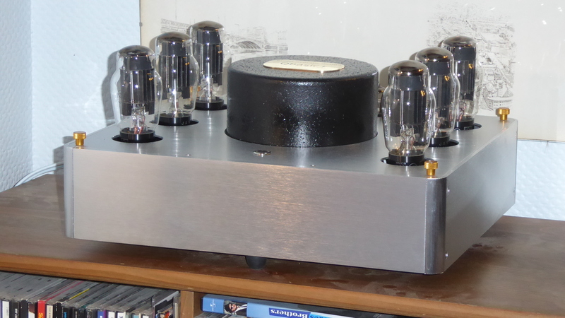
- 390R cathode resistors non-decoupled
- 150V supply and 120V p-k voltage
The driver he uses is a Willamson supplied with as high as 500VDC to give the required huge driving with a 12BH7, and the power output is 2.5WRMS 8R and circa 4WRMS 16R.
Well, this is not the same story, OK !
A+!
Last edited:
Here are the pages covering the 1954 OTL, without the magazine. A much smaller file.
Attachments
-
 6080 6AS7 OTL Amplifier Audio Magazine Jun 54 Complete_0005.jpg516.9 KB · Views: 84
 -
 6080 6AS7 OTL Amplifier Audio Magazine Jun 54 Complete_0004.jpg643.8 KB · Views: 95
 -
 6080 6AS7 OTL Amplifier Audio Magazine Jun 54 Complete_0003.jpg530.5 KB · Views: 313
 -
 6080 6AS7 OTL Amplifier Audio Magazine Jun 54 Complete_0002.jpg573.2 KB · Views: 310
 -
 6080 6AS7 OTL Amplifier Audio Magazine Jun 54 Complete_0001.jpg704.2 KB · Views: 322
Here are the pages covering the 1954 OTL, without the magazine. A much smaller file.
Thanks @jhstewart9
- I could finally load the complete initial file you have posted by... Shaking the telephone wires ! That said, I reload the 5 pages.
This morning :
- checking the @Ketje suggestion.
- improving the -B bias filtering.
I can't improve the 6080 supply filtering for the moment, since I do not have the correct parts to do it. I have a 100mVpp 100Hz ripple at -115 and +115, and a remaining faintly audible - but audible - 8mV ripple at the speaker.
Wait and See...
A+!
Last edited:
How about balancing the current from the phase inverter and the bias adjust.And with bleeders on the 115V keeps the inbalance within reason.
Also I am not very happy with the ECC83 bias of less then 0,5V, gives grid current.You can get away with it if the source has very low impedance, but not very nice.
And some protection for the grid-cathode of the ECC82 at power-up.
Mona
Also I am not very happy with the ECC83 bias of less then 0,5V, gives grid current.You can get away with it if the source has very low impedance, but not very nice.
And some protection for the grid-cathode of the ECC82 at power-up.
Mona
Attachments
- Home
- Amplifiers
- Tubes / Valves
- The ultimate OTL6080