Yes, very interestingcircuit. Can I get simillar quality results if using the speaker output winding instead of the CFB winding? Thank you. Best regards, MichalI highly recommend trying a CFB SE amplifier. It retains a lot of SE magic (immediacy and intimacy), while having clean, punchy bass and lacks that typical high level SE distortion most amplifiers do (for good).
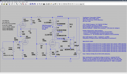
The DF of this current prototype amplifier is 7,8. I can even go higher if needed.
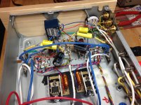
This prototype board to the far right is built with a PL82 tube.
The power supply is single transformer, tube rectified with PY82, then LC (split) LC.
Thanks to Mr. Patrick Turner, there's a lot of useful info of CFB + UL amplifiers on his website.
AmadeusMozart,
Suppose the primary of a Push Pull transformer has unequal DCRs for the Push 1/2 winding, and the Pull 1/2 winding of the primary.
Example:
Push to Center Tap DCR is 100 Ohms
Pull to Center Tap DCR is 95 Ohms
To easily fix that, put a 5 Ohm resistor in series from the Pull plate to the Pull end of the primary.
Who ever thought of that?
Just my solution
The Hashimoto OPT that I bought about 4 years ago had this difference between primary windings. Supposedly this actually improves the sound with the slight differences between the push and pull side. the Hashimoto was built accordind to the old Sansui specifications used for the HF-V6K /HF-V60 amplifiers from 1955 / 1956 that were highly respected in Japan.
FWIW Finale Audio made a SE amplifier with parallel 7591 and they used one EH parallel to a another brand 7591.
Actually the 7868 / 7591 / 6GM5 is one of the last medium power tubes to be developped and many stereo systems have been build with it. Unfortunately this tube has largely disappeared in oblivion as the guitarists never took a shine to it.
But except for the plate load (about 3 K) is behaves almost the same as the good old EL84 /6BQ5. The filament is the same but the 7591 /7868 /6GM5 are shoved into a larger envelope and with a larger plate and the screen has been changed to beam plates. This results in more H2 and less H3.
The nice thing is that you can use an EL34 OPT for it with the advantages of less interwinding capacitance and less inductance leakage between primary and secondary.
I've been collecting parts for what I call tongue in cheek a "baby Quad II" which is a SE 7868 with part UL and part cathode feedback. Gery (Transcendar) was so kind to wind a couple of custom OPT before he stopped taking orders. The tarnsformer is properly interleaved and the secondary windings is not one contious winding with taps for 4 and 8 ohms but is more complex.
Due to having moved house and since then having health issues I have not been able to progress - hopefully later this year (after finishing some chores around the new place) and otherwise early next year.
A tweak here and a tweak there in LtSpice and then trying something else again ended up giving me attached draft. But proof will be in the pudding so to speak and undoubtly some tweaks will be required. (which why I acquired some more test gear - had a Marconi distortion factor meter in the past but sold it as I did not expect to build anything anymore. But tube amplifiers have a charm in itself to them and it is almost like a drug - I've got to build another one <wink>.)
While collecting parts I also acquired a HP 339A distortion analyser and brought it back from the brink. I also have a PicoScope but unfortunately is not senstive enough for proper testing so also bought a focusrite 2i2 to use with REW.
I've got 6 genuine NOS 7868 of which four where I know which shop they were bought from (no fakes there) and the two others came from the US from a "reputable seller". In the UK I picked up two unusued NOS EL506 (Brimar's version of the 7868 but with a magnoval base instead of Novar. IMHO I feel the EH 7868 is based on this tube)
It took me a while to find the tight tube for it and in the end the ECC81 ( ~~12AT7) proved to be one of the better choices when run in SRPP mode. I'll be using one tube for the "top" triodes" wth elavated filament and another ECC81 for both "bottom" triodes.
The 7868 / 7591/ 6GM5 is a tough little tube, reportedly to be almost indesctructable when run within limits. In the days it came out it was often pushed beyond its maxmimum ratings and still survived for long periods. Some time ago I read posting from someone and he calls the tube "next to indestuctable" and having them 20 000 hrs in his amp and still going strong.
Enjoy!
AM
edit: It is capable of approx 7 watts out of this design but distortion rises to around 1.5% at onset grid current and the tube will be running right at the limit of absolute maximum ratings.
Attachments
Last edited:
AmadeusMozart,
Suppose the primary of a Push Pull transformer has unequal DCRs for the Push 1/2 winding, and the Pull 1/2 winding of the primary.
Example:
Push to Center Tap DCR is 100 Ohms
Pull to Center Tap DCR is 95 Ohms
To easily fix that, put a 5 Ohm resistor in series from the Pull plate to the Pull end of the primary.
Who ever thought of that?
Just my solution
The difference in the Hashimoto was more than that and as mentioned before it was based on the original design by Sansui (apparently the same people at Hashimoto made the transformers for Sansui too). And such I was loath to change / tinker with the output stage.
AmadeusMozart,
Thanks for making me think more clearly!
As a result, I am having second thoughts about the degree of importance of push pull transformers needing perfectly balanced DCRs.
Suppose a 7591 is operated in pentode mode.
The plate impedance, rp, is 29,000 Ohms.
A 100 Ohm primary DCR un-balance will have very little effect: 29,100 versus 29,000 Ohms.
It will not have a noticeable effect on the DC current balance of two plates, and will not have a noticeable effect on the AC balance of the two plates.
Suppose a 7591 is operated in Ultra Linear mode.
The plate impedance, rp, is perhaps 3,400 Ohms.
A 100 Ohm primary DCR un-balance will not have much effect: 3,500 versus 3,400 Ohms.
It will not have much effect on the DC current balance of two plates, and will not have much effect on the AC balance of the two plates.
Suppose a 7591 is operated in Triode Wired mode.
The plate impedance, rp, is perhaps 1,700 Ohms.
A 100 Ohm primary DCR un-balance will have some effect: 1,800 versus 1,700 Ohms.
It can have an effect on the DC current balance of the two plates, and can have an effect on the AC balance of the two plates.
. . . Triode Wired mode is where the un-balanced primary DCRs has the most effect.
Does that make sense?
Given that the pair of tubes often has more rp imbalance (even for a "matched" pair - and I'm not even talking about what happens after a year or two of operation), I would't really bother that muchSuppose a 7591 is operated in Triode Wired mode.
The plate impedance, rp, is perhaps 1,700 Ohms.
A 100 Ohm primary DCR un-balance will have some effect: 1,800 versus 1,700 Ohms.
It can have an effect on the DC current balance of the two plates, and can have an effect on the AC balance of the two plates.

TG,
I have experience with push pull amplifiers, using matched 7591, 6L6, KT66, and KT77 tubes that I use in amplifiers that I designed.
All of those amplifiers have individual self biased tubes, and most are either in UL or Triode Wired modes.
Over hundreds, and even in some cases 1,000 Hours or more, and a few years, the tubes remain very well balanced.
The only negative feed back that I use on these push pull amplifiers is the very local feedback obtained when they are in UL and triode wired modes.
And because the 2nd harmonic distortion is very low, I also expect that the plate resistances, rp, are very well matched.
Unmatched rp values do not cancel the 2nd harmonic very well, depending on the tube's operating mode, and the plate to plate primary impedance.
Just my experience, and just my opinion.
Your Mileage May Vary.
Last edited:
Given that the pair of tubes often has more rp imbalance (even for a "matched" pair - and I'm not even talking about what happens after a year or two of operation), I would't really bother that much
There were manufacturers that when the tubes were within 20% they were considered "matched". Within cathode bias in push pull it does not matter too much but in fixed bias any differences between tubes get amplified plus gives rise to the risk of thermal runaway. IMHO the disadvantegs of fixed bias outweigh the advantages.
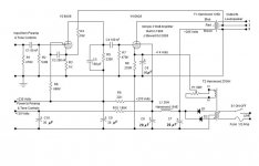
I have no idea how this would compare to the CFB design posted by 50AE, but here's a link to a SE 6BQ5 amp I built last year using local FB from the speaker output winding.Yes, very interestingcircuit. Can I get simillar quality results if using the speaker output winding instead of the CFB winding? Thank you. Best regards, Michal
Voice of Music SE 6BQ5 w/Local NFB Build | Audiokarma Home Audio Stereo Discussion Forums
It's a bit different in that there is no input tube on the amp chassis. The stock configuration used a preamp section connected with an umbilical. I wanted to be able to use a variety of preamps with it and, since I was running the 6BQ5s in pentode, some FB was needed so I was forced to use a local FB scheme.
The final schematic is at the end of the thread.
If I were building this from scratch I'd use a larger chassis so I could replace all the electrolytic caps with DC Link films. I'd also probably use a choke with more inductance in the PS. The one I used was just a junkbox part that happened to fit so I thought I'd give it a try.
I'm actually listening to it now with what is essentially a passive preamp - I'm streaming a jazz radio site from my old Mac Mini to an Airport Express via WiFi which is connected directly to the inputs with volume controlled on the Mac.
So, I guess it's in Spud configuration at the moment.
It will play louder using a preamp with gain but it's got plenty of volume for me using this setup, even though it's in another room. And the sound is truly excellent.
I'm sure OTs with CFB windings are available but I've never seen one so I assume they aren't very common.
Last edited:
I have experience with push pull amplifiers, using matched 7591, 6L6, KT66, and KT77 tubes that I use in amplifiers that I designed.
Can you post or direct me to good 7591/7868 parallel PP schematic?
Thx,
Jim
oemcar,
Sorry, I do not have a Parallel push pull 7591 schematic.
And to find a good one, how would I know if it is good or not (not listened to any Parallel push pull 7591 amplifiers, only single push pull). If I found a schematic on the web, I would at lease have to analyze the Parallel push pull circuit completely.
However, there is hope for you . . . take a look at a good 7591 PP amp, it is a good start.
Start with a good push pull 7591 amplifier. Pick one that has individual self bias for the output tubes.
Now modify it for Parallel push pull:
Increase the B+ current capability by 2X, and make sure the supply impedance is 1/2 of the original impedance.
Increase the transformer laminations by 2x to deal with 2X the output power (but use a primary winding of 1/2 the impedance, and 1/2 the primary DCR).
The 7591 g1 resistors are in parallel (1/2 of a single tube), and the g1 input capacitance including miller capacitance effect is 2x that of a single tube; So you have to design the driver to drive 1/2 of the original g1 grids total impedance.
Double the number of output tube self bias RC networks (continue to use individual self bias for each tube).
Use well matched output tubes (4 matched per channel).
The B+ voltage, driver voltage swing, and output plates voltage swings all remain the same as the original push pull amp.
The only change is the power mains Watts draw is 2X, the output power Watts is 2X, and the weight is 2X.
2X the power at the same distortion % as the original good amplifier.
That is just one way to do it (and easy to calculate).
How does that work for you?
I discussed all these relevant factors in a joint article with 2 more engineers in
Glass Audio's very last issue, Volume 12, Number 5, 2000.
The article we wrote was the cover article: "Paralleling Tubes Effects".
Yes, you have to use all the findings and principles in the article, even though the article included 600 test measurements of 20 dual triode tubes. Triodes, Real Tetrodes, Beam Power, Pentodes, the principles and requirements are all the same when paralleling.
I admit, you may never find that article on the web.
But I already just listed all of the important factors in this Post #33, so you do not need to read the article.
I also presented the findings of the article at one of the VSAC conferences in Silverdale Washington.
VSAC . . . Vacuum Tube state of the Art Conference.
Good luck building a Parallel push pull 7591 amplifier.
Have fun, and good listening too!
I am hoping to find the time and energy soon . . . to build a 2 stage 7591 balanced push pull amplifier to use with my balanced CD player output.
Last edited:
Duplicating original drive and bias circuits and adding 2 output tubes in parallel w/ OT having 1/2 impedance, twice the wattage is not too hard to follow. If was SS, I wouldn't hesitate to just get the breadboard and start experimenting.
Tube circuits, however, are less forgiving- 400v can turn experimenting into a fireworks show quickly, especially if supply current is doubled. This is why, at my current experience level w/ tube designs, I prefer to have an existing baseline to start with. Even the guys who use sim programs come up w/ designs that look good on 'paper', but fall short in practicality and results.
Thats where experience comes in... and as Harry Callahan says... "a man's got to know his limitations". So I'll subscribe to your project, when you get there.
Jim
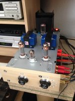
RH84 gets some flak around these parts at times, but I built one as published several years ago and it was a nice single-ended amplifier IMO.
If you're interested in feedback schemes, it's certainly something to play with. Sticking a pentode in the front end (for an all pentode amp) would actually make the feedback more effective, too. I'm bet there's a modified version of the schematic somewhere that does this with a 6AU6 or something.
I built this one in 1968. It runs every day in the shop. All inside a Hammond 8x12x3 chassis. If I built it today I'd use one of the more recent Hammond SE OPTs.
Attachments
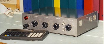
Hi,
My vote as well for RH84, since you have OT, just PT with tubes & sockets + few parts and you are done!
For power trafo maybe cheap AskJanFirst TRA400 with tube rectifier windings: Ask Jan First ® ; electron tubes and more
My old but very nice sounding RH84 with Edcor 10W OT...
My vote as well for RH84, since you have OT, just PT with tubes & sockets + few parts and you are done!
For power trafo maybe cheap AskJanFirst TRA400 with tube rectifier windings: Ask Jan First ® ; electron tubes and more
My old but very nice sounding RH84 with Edcor 10W OT...
Attachments

Btw, with LTSpice if you do have the output tube model, you should be able to simulate any CFB schematic.
For the 70th Birthday of my father, I put together a full transformer and choke kit for a PC86 + PL83 amp and I had three days to do it. It's a capacitor coupled pentode SE CFB amp. No time to test, so I relied on my previous experience with the PL82, the simple formulas from Turner Audio and an LTSpice sim. It worked flawlessly, yesterday he managed to put together the amp and it's singing now.
For the 70th Birthday of my father, I put together a full transformer and choke kit for a PC86 + PL83 amp and I had three days to do it. It's a capacitor coupled pentode SE CFB amp. No time to test, so I relied on my previous experience with the PL82, the simple formulas from Turner Audio and an LTSpice sim. It worked flawlessly, yesterday he managed to put together the amp and it's singing now.
- Home
- Amplifiers
- Tubes / Valves
- Best EL84 SE amplifier?