Hello.
May I use a 6sn7 to drive 4xkt88 UL class B power amp, please? Plates are supplied at 650v arround, common 100k grid leaks, fixed bias operation.
Thinking more to supply 6sn7 B+ at 600v around in 47k plate loads with -80 ,-100v in driver common cathode. The distortions are not quite an concern as I intend MI aplication, just wonder by driving capabilities pls. I suppose bias voltage will be -85 -90V around so the driver should be swing 250V pk-pk at least. Should it work ? Thanks.
Last edited:
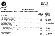
If you have the usual 8 mA current for one section of a 6SN7, and a plate resistor of 47K you will have a voltage drop of 376 volts, with 224 Volt on the plate. This is within tube limits.
Do you use the 6SN7 as phase shifter, using one or both triodes? Or as a PP amplifying stage? A diagram will be helpfull.
Regards, Gerrit
Do you use the 6SN7 as phase shifter, using one or both triodes? Or as a PP amplifying stage? A diagram will be helpfull.
Regards, Gerrit

Attachments
Thanks for kind replies.
Yes the power stage it works in class B operation. The supply is huge 650v to plate and screens. It is a power stage from Simms Watts 200UL. I ask just for the driver. It will be well coupled to a 12ax7 ltp inverter. Large swing is critical due to high voltage bias point. And yes the op point will be within the limit thinking with a plate idling at some 240v around there will be enough room to swing DC+AC....think absolute max value 500v, but don't remember exactly I saw 1500V for 6sn7...!!!.....thanks
Yes the power stage it works in class B operation. The supply is huge 650v to plate and screens. It is a power stage from Simms Watts 200UL. I ask just for the driver. It will be well coupled to a 12ax7 ltp inverter. Large swing is critical due to high voltage bias point. And yes the op point will be within the limit thinking with a plate idling at some 240v around there will be enough room to swing DC+AC....think absolute max value 500v, but don't remember exactly I saw 1500V for 6sn7...!!!.....thanks
Last edited:
Large swing is critical due to high voltage bias point.
In case the output stage operates at class B, the voltage swing is not the biggest problem.
It is the grid (g1) current the driver stage must be able to supply too.
This means that 6SN7 should operate as cathode follower connected directly (without capacitor) to control grids of output tubes. The bias of output tubes is also supplied by driver stage.
It is not possible to give right instructions without seeing the schematic of the amplifier.
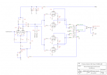
The construction principle of driver arrangement is like in attached schematic (Heathkit W6M):
https://www.ampslab.com/SCHEMATICS/HeathkitW6M.jpg
Last edited:
That's class B2, but the OP hasn't said if it's class B1 or B2. My guess is B1 so no grid current required. A 6SN7 could do that. It might be heavily loaded by the grid leaks, sure, but this is for MI.In case the output stage operates at class B, the voltage swing is not the biggest problem.
It is the grid (g1) current the driver stage must be able to supply too.
Think was not...The power tubes was drived directly from 12ax7 plates of ltp inverter with 220k common grids loads for 4xkt88..???. I intend to fit a hefty driver in between and reduce those unsafe grid leak to 220k per tube, keeping iddling dissipation under 35w as data sheets stated.
Attachments
Last edited:
Would you waste a Quad of KT88 tubes on a wimpy 12AX7 driver?
12AX7 tubes are good at something else.
The push pull parallel KT88 tubes are in ultra linear mode.
The often forgotten Miller Effect Capacitance is present on Ultra Linear output stages.
The Screen has voltage gain, and is moving in the opposite direction of the control grid
. . . the very definition of Miller Effect Capacitance.
The parallel configuration Doubles the Miller Effect Capacitance.
Well, all that might be a plus, because I bet the Miller Effect Capacitance and the 12AX7 high plate resistance, rp, and the high resistance 12AX7 plate loads, RL, will form the dominant high frequency pole.
Or, maybe the 100pF across the 12AX7 plates is the dominant high frequency pole.
Dominant high frequency poles are often required to use global negative feedback.
It all might work together, or it might not.
One more thing, since the LTP is not using a true current sink (yes sink, not source), the 12AX7 plate resistors, RL, are not equal resistance.
That means you have 2 high frequency poles that do not have the same frequency response, and more importantly do not have the same phase lag.
82k in parallel with the triode rp, and 100k in parallel with the triode rp.
P.S.
Most important:
Oh, you have KT88 tubes with 220k control resistors to the fixed adjustable negative bias.
You have to hope that the KT88 tubes are much better than their specs (100k per tube in fixed adjustable bias).
Since the control grids are in parallel, and using fixed adjustable bias, you need 50k there, not 220k there.
Thermal run-away will take over . . . sooner or later.
A 12AX7 is not going to drive 50k Ohm output tube G1 resistors to the negative bias.
Last edited:
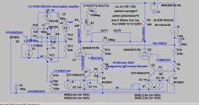
You can try this type of drive, with a PCM1794(2x pcm1798) dac Iout with 6.2ma offset current used to bias the 6SN7 valve or a dac without current offset, like the more modern ones as the new dacs have around 4...8ma output : 6N7 Russian valve can be used as well.
Attachments

Last edited:
It all depends on what tubes you use, what manufacturer, NOS, brand new, etc.
And Ultra Linear can be hard on tubes.
Start with a 450V B+.
The plate swings down 400V to say 50V, while the 40% tap, and screen voltage swings down 160V to 290V.
Go look at the screen current at 300V screen, and 50V plate.
It does not spend much time there, but calculate 300V times that peak current to see what is going on. Wow!
Do not get me wrong, I designed: one push pull amp with ultra linear, and one single ended amp with ultra linear.
I like them both.
Do not forget, unless the tubes are perfectly matched, one will always draw more current than its parallel mate.
At least get some individual 10 Ohm resistors in each cathode to ground.
You can measure the match when new, and as the tubes age too.
Two more coupling caps, and two more bias pots gives individual bias adjustments for you.
I normally prefer to use individual self bias resistors, and individual bypass caps across the resistors.
A Lot less parts than individual fixed adjustable bias circuits, and individual 10 Ohm sense resistors.
You get less power output, but I never could easily hear the difference between 40 Watts and 50 Watts.
-1dB anybody?
And our Logarithmic response ears hear a 10dB difference in electrical/acoustic power as a 2:1 perceived loudness difference.
To each his own.
Your mileage may vary.
Last edited:
It all depends by aplication and in MI aplication,where dynamic range is different a little bit headroom can made a bunch of difference, not by loudness but tone as itself. I bet those amp I triy to modify get a lot of compression when pushed hard without to endanger the power tubes in lack of resources to drive it enough.
Last edited:
Hello.
May I use a 6sn7 to drive 4xkt88 UL class B power amp, please? Plates are supplied at 650v arround, common 100k grid leaks, fixed bias operation.
Thinking more to supply 6sn7 B+ at 600v around in 47k plate loads with -80 ,-100v in driver common cathode. The distortions are not quite an concern as I intend MI aplication, just wonder by driving capabilities pls. I suppose bias voltage will be -85 -90V around so the driver should be swing 250V pk-pk at least. Should it work ? Thanks.
you may want to introduce an RC to supply your 6sn7 to decouple the supply from the 600vdc psu..
the RC coupled tables at the RCA tube manual will give you values of resistors for either maximum output swing or maximum gain...
in your case, maximum output swing is more desirable than maximum gains..
a scheme would be nice to see..
650vdc for both plate and screens will be asking for trouble, especially ith new production tubes..
Last edited:
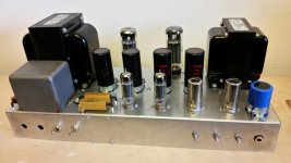
This was a project made from scratch years ago: 2kt90 UL, el84 drived. Got hundred watts at 540V with hammond irons. I know how a pair of kt sound if are properly drived. The amp I try to modify now is in original condition. I don't want to butcher it , but I can insert a proper driver in between to see what I get...
Attachments
Last edited:
It is interesting to see what the original amp was, and that it had nothing to do with most of the schematics that were posted in the thread.
Pretty hard to make an educated guess recommendation based on the above.
Sometimes, it helps to start with the original, tube types, topology, etc.
With compression, clipping, and driving the amp beyond linear range, etc.; I ask:
Is this for a Hi Fi application, or for an electric guitar application?
Last edited:

- Status
- This old topic is closed. If you want to reopen this topic, contact a moderator using the "Report Post" button.
- Home
- Amplifiers
- Tubes / Valves
- 6sn7 driver question