The effect of this delay will depend on the (unknown) capacity across R2. A 10 second delay is a bit short when you want your tubes to start conducting before the relay shorts R1. Some tubes need more than a minute to heat properly. For higher safety with high voltages you could put R1 in the ground wire instead. A value of 33K looks pretty high for me, but this will also depend on the B+ load. In my supplies I have used much lower values, from 47 Ohm to 1K.
Regards, Gerrit
Regards, Gerrit
In theory, R1 will charge the capacitors up to 5/6th of the available B+ until the tubes conduct enough current to load the supply which is about 10 seconds for signal tubes. That's my thinking anyway. I'm not trying to protect the tubes, just the 600V capacitors.
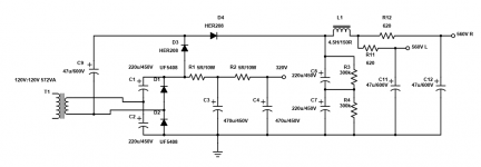
EDIT: Here's the PSU in question. I was thinking the above inserted at C8/L1. C11 and C12 are the caps I'm hearing sizzle on start up once in a while...
EDIT: Here's the PSU in question. I was thinking the above inserted at C8/L1. C11 and C12 are the caps I'm hearing sizzle on start up once in a while...
Attachments
Last edited:
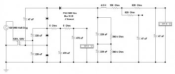
Under no load the HV is very high. There needs to be more fixed
resistor load across each of the filter caps to safely discharge when shut down.
As is the time constant is 122.4 seconds, way too long for safety.
Dropping resistors after the choke is kinda odd. But it will work,
might get some strange results.
5R between each of the caps in the LV section won't do much, better if 50R.
Attachments
I know. That's the point of trying to limit it to 600V while it's warming upUnder no load the HV is very high. There needs to be more fixed
resistor load across each of the filter caps to safely discharge when shut down.
As is the time constant is 122.4 seconds, way too long for safety.
Dropping resistors after the choke is kinda odd. But it will work,
might get some strange results.
5R between each of the caps in the LV section won't do much, better if 50R.
Peak current is more than 1A. Idle is 400mA. hence using a total of 10R with large-ish caps. 100R total is WAY to large in this case, and since that part of the PSU only powers the push pull output stage, the ripple cancels in the OPT. It's only about 300mV anyway.
122.4 seconds is perfectly safe IMHO. It would take longer than that to disconnect and dismantle it! Even then, this assumes it didn't work. If the amp is running and then turned off, the circuit uses the power in a few seconds before it's cold.
Last edited:
Better be safe, always design for worst case.
Worst case is with all the tubes out, no load. Then shutdown, disconnect.
Then forgot the caps are loaded.
What you don't see in the schematic is the LEDs running from dropping resistors. The one on the 560V line wastes about 2 watts... They also give a visible indication of charge.
When I was using caps big enough to hold charge for 45 minutes I used to use a relay to short them to ground through a 4k7 power resistor for faster bleeding. In order to have the caps drain in like 15 seconds, you would need to waste too much power IMHO.
Safety dictates you should assume the power is on/circuit is live/caps are charged.
If you open a tube amp and start prodding around without checking the voltages with a meter first, you are foolish IMHO.
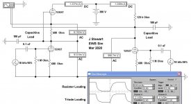
Response to Square Wave, Triode vs Resistor Loading
In this Sim the triode loaded vers is compared to the resistor loaded vers driven by equal square waves of 0.1V P-P. The capacitive loading is increased to look like a short piece of coax. The resulting signals are offset to result in a clear display.
The triode loaded side appears very slightly better,
Would we hear that? Not me for sure!. Perhaps others with bats ears tho.
Attachments
Câlice...
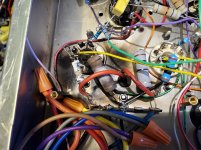
So the 36LW6 amp is being reborn as a 6P31S (or 6DQ6B) amp...
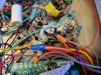
Yesterday after 2 weeks of 24/7, I smelled burning... Turned off the power stage... This morning I opened it up to find this!
That white snake thing is actually burnt insulation like the red wire on the "good" side. That thing was flame proof but I'm still surprised there was no fire... The big resistors were 10R 5W MO, the smaller ones 250R 2W MF...
Funny thing is, the 10R in the second photo still works despite the cracks and burning!
Because I don't trust two tubes that were stressed like this along with two that weren't, I'm changing this to 6P31S. It will idle at about 50mA/320V, and now use VPT12-4170 as OPTs instead of VPT18-5560.
I will build a new stand alone amp using the VPT18 transformers with 6P36S most likely.
If anyone needs 4 36LW6 tubes, two of which are slightly used,but have no keyway, the other two are with the keyway but have been run HARD...
So the 36LW6 amp is being reborn as a 6P31S (or 6DQ6B) amp...
Yesterday after 2 weeks of 24/7, I smelled burning... Turned off the power stage... This morning I opened it up to find this!
That white snake thing is actually burnt insulation like the red wire on the "good" side. That thing was flame proof but I'm still surprised there was no fire... The big resistors were 10R 5W MO, the smaller ones 250R 2W MF...
Funny thing is, the 10R in the second photo still works despite the cracks and burning!
Because I don't trust two tubes that were stressed like this along with two that weren't, I'm changing this to 6P31S. It will idle at about 50mA/320V, and now use VPT12-4170 as OPTs instead of VPT18-5560.
I will build a new stand alone amp using the VPT18 transformers with 6P36S most likely.
If anyone needs 4 36LW6 tubes, two of which are slightly used,but have no keyway, the other two are with the keyway but have been run HARD...
Attachments
Looks like you were doing an accelerated life test, The manufacturer would be interested in the operating conditions & your results.It was triode, and so far I've only had it happen with US tubes... the Soviet ones have been pretty well behaved. I was also using 330k grid leaks. Perhaps a lower value would have helped...
Ya... The Soviet tubes list 1M or 2M2 usually. It's true though, these tubes worked for months with 100k grid leak. They were on for about 1 week 24/7 before both of those tubes ran away at the same time. I think there might have been an error with the biasing board because I've only ever seen one tube run away at a time but who knows...
The 6DQ6B that I'm switching to while I wait for the 6P31S lists 1M as the maximum grid leak, so it should be good.
The 6DQ6B that I'm switching to while I wait for the 6P31S lists 1M as the maximum grid leak, so it should be good.
Last edited:
The 330k could be the culprit. But even Tubelab George has had LW6’s run away single ended. I’ve seen bias drift up when running sweeps at a high bias during “experiments”. It seems like ALL devices, sand or vacuum, that are really designed for switching duty don’t like to sit there and dissipate DC at high voltages (remember the real anode is the screen grid). I think I would only do pentode with 150 on g2, and maybe 30mA, but that’s probably not consistent with your design goals. And I’d still drive it directly with a follower. Even 6550’s get that treatment in my current build in progress.
I was sort of in the process of collecting LW6’s (and a couple other 20-25W octal types), but I’ve put a complete halt to spending for the duration. Even at $11, unfortunately, no more electronics ordering. Only to resume when the crisis is over, if still gainfully employed.
I was sort of in the process of collecting LW6’s (and a couple other 20-25W octal types), but I’ve put a complete halt to spending for the duration. Even at $11, unfortunately, no more electronics ordering. Only to resume when the crisis is over, if still gainfully employed.
One thing is for sure... The tube can move current! I've never seen a 5W 10R resistor virtually catch fire along with it's 250R screen resistor.
I had one 6P45S run away but it just glowed orange hot and cracked the glass, the resistors in the amp were fine. Now it seems to make my design more robust, I need to make the resistors higher power. 5W screen and 10W cathode sense maybe...
I'd rather a bad tube just be replaced without having to repair the circuit, too.
If the tube runs away, yes. Even in normal operation I expected peaks of about 800mA, but overengineering the resistors makes one less failure mode.
In reality, the bias board has an "open collector error output" that could be used to cut the power if the tubes can't be biased, but I don't understand that yet. I assume I could use a transistor to drive a relay. If I understand it right, it means that pin will be at ground if there's an error.
The aluminum resistors need heatsinks... I'm thinking MO types... I'm still using the 5W jobs, since this amp will now use 6DQ6B or 6P31S...
I wonder if running the screens through diodes would stop then from becoming an emitter in an overload situation...
even Tubelab George has had LW6’s run away single ended.
I killed 4 of them before ripping the amp up and reusing the parts for something else. It was a class A single ended design where the tubes were triode wired with a 100 ohm 2 watt resistor from grid to plate. All went into "slow cook" runaway at idle. The 2 watt resistor was burnt, but not open circuit in all cases, indicating excessive screen current.
Koda's tubes are Sylvania made. Mine were 2 X GE, and 2 X Sylvania. The amp was used for my computer speakers (Yamaha NS-10M's), and was turned on whenever the PC was on, and saw a lot of idle or very low volume time. This all happened about 10 years ago.
The tube can move current!
It's peak current RATING is 1.4 Amps.....and that's the spec. It will do more, but my power supply limits at 1.7 amps. I took a rather crusty looking old 36LW6 tube and subjected it to some "testing" to draw it's curves at places not shown in the data sheet. It WILL dissipate over 600 watts for long enough to read the meters for a manual curve tracing (about 500 mS). The lines are grid voltages in 5 volt increments with +5V on the top. Screen voltage was fixed at 150 volts.
Attachments

I wonder if running the screens through diodes would stop then from becoming an emitter in an overload situation
I found that to be useful in screen driven amps where the screen gets hot at the positive peak of the drive cycle where the screen is at +200 volts and the plate is at 30 volts. Then when the cycle reverses the screen is near zero and the plate is over 1KV resulting in a bright white flash!
I experimented with driving both G1 and G2 to mitigate these effects, but still blew up tubes. I have accumulated a lot of 6BQ6 and 25DN6 types at an average cost of 50 to 65 cents each, so I can afford to do these tests.
In triode where the screen and plate are at nearly the same potential, the glowing screen has no receptors for its excess electrons, at least not a high current path.
The death of 4 x 36LW6's put an end to my triode wired big sweep tube experiments.
I have however seriously abused plenty of 6AV5's in triode without a single failure over several years.
More recently I had two 6W6GT's fail from the same slow cook idle runaway. One was a crusty old tube, so I replaced it with a brand new tube and it died the same death after about a year. I got a big box full of 6DG6GT's for cheap. They are the same tube, so I plan to explore this phenomenon further, but tube death often takes a long time, so I haven't gone any further.
The 6W6 / 6DG6 is exactly the same tube as the 50L6, 25L6, 25W6, and 12L6 except for the heater ratings. These were used in millions of old radios and TV's for audio and vertical sweep, and often played for years continuously without failure at 150 volts or less. I have cranked 30 watts from a pair of 6W6's in push pull on 340 volts of B+ without a problem. That amp is still kicking with it's original tubes after almost 3 years. I have the screen grids at 125 volts.
The issue has to be related with screen grids at high voltages.
- Status
- This old topic is closed. If you want to reopen this topic, contact a moderator using the "Report Post" button.
- Home
- Amplifiers
- Tubes / Valves
- New build: 36LW6 integrated amp with phono avec SMPS/DC Boost.