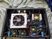
So the PSU is finished...
It provides 12V, 36V, -110V, 280V, 330V, and 560V.
The box it powers will have RIAA phono, gain stage for 6E2, and a gain stage with buffer, all triode with active load. This will feed an all triode (connected, they are 36LW6 strapped) PP output stage.
More detail to come on this Koda channel.
Enclosed are preliminary artworks.
Attachments

So the PSU is finished...
More detail to come on this Koda channel.
Enclosed are preliminary artworks.
Hmmm! Interesting! I will follow this Koda channel with eagerly. I have a dozen or so 26LW6s tucked away.
Ya, that PSU is packed for sure, but it puts out 12V, 36V, 280V, 330V, 560V, -110V, and 6VAC over 11 wires / three connectors! 
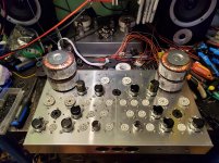
Wait until you see how "packed" the IA will be... 24 tubes (so far) aling with a relay input board, a biasing board, VU meter board, and hopefully Bluetooth board, too. That's why I put all the power modules in the PSU this time... No chassis real-estate.
Tonight, I will start to drill the holes in the chassis I think...
Last edited:
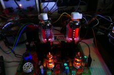
On a side note. Tonight I put 6P3S in place of KT88 just to see how it would work... (560V B+, 4k3 Ra-a, 50mA idle) and to my surprise, some 21W 6P3S tubes work fine. Others exhibit a hot spot on the heat fin of the plate like in the picture. It was a dull red in real life, not the pink you see in the photo.
Attachments
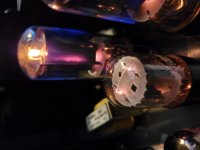
Most camera sensors "see" infrared and display it as pink. I have plenty of pictures featuring tubes with pink plates. As you crank up the power dissipation the real red glow becomes dominant. My old Sony camera would show pinkish plates even when NO plate glow was visible in a dark room. The two Panasonic Lumix cameras I use now are not as IR sensitive as the Sony was.
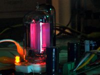
This picture shows a couple of 36LW6's running a bit over the dissipation spec....OK a lot over the spec. Still, none of this glow is visible with the room lights on.
Third picture was taken with the old Sony several years ago. None of this glow was visible with the lights on.
This picture shows a couple of 36LW6's running a bit over the dissipation spec....OK a lot over the spec. Still, none of this glow is visible with the room lights on.
Third picture was taken with the old Sony several years ago. None of this glow was visible with the lights on.
Attachments
Last edited:
pic was taken with a Note 10+... Pretty good camera really.
My last Samsung was a Note 2. My oldest grandson still uses it for a camera and video game player. The new Apple and Samsung phones are out of reach for me price wise and I am not a big cell phone user.
Pictures and video are important to me, but both of my Lumix cameras together cost less than a Note 10. The FZ-1000 has taken over 375,000 pictures in 2 1/2 years, gotten rather wet twice, and still works great.
I use a $200 Motorola phone from Amazon, and it takes decent (but not great) pictures and video. I used it to shoot this entire video and upload it unedited to YouTube. The phone was in one hand while I played with the power supply and scope with the other. That's the reason for the shaky pictures sometimes.
YouTube
I don't know if you ever saw it, but I have stated in the past that I killed 4 different 6LW6 tubes by operating them in triode mode. The first two were at 400 volts of B+, and the second two in the 325 volt range. All were operated in class A Single Ended, and all died a "slow cook" death where the tube current gradually crept upward until a runaway event occurred resulting in a blown fuse or worse. None of the tubes were stable enough to use again after the initial runaway. ALL occurred during extended idle periods, which is worse case for a class A design. The first two occurred within a few months, but the last tube lived for nearly a year before flashing over internally. Screen grid dissipation was well below spec, but over voltage at idle. It IS possible that these were bad tubes, since they seem to act "gassy". The other tubes from the same source have been OK.
I have seen similar failures in 2 X 6W6GT tubes that were operated within the plate and screen voltage and dissipation limits.
I just thought to mention my findings, and they are probably not a concern unless you intend to run in class A near or above the 35 watt dissipation range.
The glowing 36LW6 tubes in my pictures are running class A at about 60 watts, but the screen grids are regulated at 150 volts.
I've been lucky so far I guess... I've already run these tubes (300V, 120mA) in push pull (1k or so Ra-a) for a few months and there worked fine. This amp will use an autobiasing board so if the tube wants to conduct more, the board will bias the tube colder to compensate. I oversize all the components too, so if the tube goes it won't take out anything with it. If/when these tubes fail, the amp will be converted to 6P36S or similar.
Well the other amp that I took the KT88s out of yesterday and replaced them with 6P3S has been running for 24 hours now at 560V UL mode @ 50mA. 28 Watts from a 4$ 21W tube isn't bad at all. I haven't been blasting it, but yesterday when there was a tube starting to redplate, turning up the volume made it stop rather quickly so I figure it's transferring the power into the load instead of dissipating it.
This is the record of how long you can beat the crap out of 6P3S before they die... The autobiasing board will make sure they keep flowing 50mA until they just run out of current to give (and sounds like la marde).
Tomorrow, I'll hopefully complete the drilling and mounting of xfmrs and sockets on the chassis of the new amp.
Last edited:
so I figure it's transferring the power into the load instead of dissipating it.
That's exactly what happens.
In a class A amp the tube sees worst case at zero volume, all of the power supply's power is burnt up in the tube. At full volume the dissipation is the lowest since some of the power supply's power is converted to audio power.
In a pure class B amp, its the other way around. The idle current is zero, or close to it, so there is no power burned up in the tubes, other than heater power. At full tilt, the power drawn from the supply is maximum, and the tube dissipation is near maximum as well. Maximum dissipation could be at full power, or slightly below full power, depending on the load impedance.
In a class AB amp maximum dissipation can be anywhere from near idle, to near full power, depending on how hot (closer to class A) the amp is biased, and how it's loaded. Most class AB amps see maximum dissipation between half and 2/3 power. For many of my amps, maximum dissipation can be determined by watching the plates in a dark room.
Note, a "class A" amp leaves class A as soon as, or slightly before is sees clipping. That class A Fender Champ is nowhere near class A when you plug in a pedal board set on KILL and dime the volume knob!
In my case, it's triode connected and AB1, and I run them hot... ~300V/100mA into ~1k Ra-a (~80W with ~8W class A IIRC). I could in theory rig a switch to make 4kRa-a and have a solid 25W class A but it seems wasteful.
For my monoblocs, my testing shows 112W sine 30Hz... TCJ Push Pull Calculator (I call it ppcalc) gives the attached when adjusted to real world output or close enough to it...
For my monoblocs, my testing shows 112W sine 30Hz... TCJ Push Pull Calculator (I call it ppcalc) gives the attached when adjusted to real world output or close enough to it...
Attachments

> Most camera sensors "see" infrared and display it as pink.
IIRC, the basic Silicon sensor picks up IR very well. Even body heat. So well, that it can "see through clothes". Better than those X-Ray Specs in the comic books. And that most consumer cameras had IR filtering to reduce embarrassment.
Of course they were not figuring on George's hot-tube fetish.
IIRC, the basic Silicon sensor picks up IR very well. Even body heat. So well, that it can "see through clothes". Better than those X-Ray Specs in the comic books. And that most consumer cameras had IR filtering to reduce embarrassment.
Of course they were not figuring on George's hot-tube fetish.
And that most consumer cameras had IR filtering
The old Sony I refer to is a DSC-F828 "pro-sumer" 8 megapixel camera from 2003. It was the first Sony to use Compact Flash as well as their proprietary Memory Stick, switch selectable. It "sees" tube glow that is not there and also makes some people's bare skin look a bit pink under some conditions.
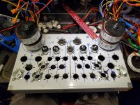
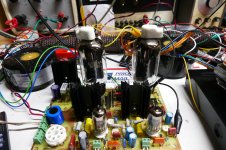
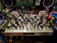
Well it's starting to look the business now that the sockets are populated!
I've decided on the tube compliment.
Phono will be Aikido style (without the noise nulling) and use 6N14P -> 6N24P -> 6N2P -> 6N3P.
Line will be the same style, but using 6N24P -> 6N6P.
VU meter will use a triode strapped 6J1 -> 6E2.
Power stage will be my typical 6F12P VA -> 6F12P PI -> 6N8S VA -> 36LW6 triode strapped.
Besides the 36LW6, the capacitors cost me more than the tubes!
Attachments
Last edited:
I did not appreciate the scope of that project until I saw this picture. I know that my attention span would not allow me to complete something of this magnitude. Getting this far is the easy part......wiring it all up? I have far less complicated projects in boxes that never got finished.
- Status
- This old topic is closed. If you want to reopen this topic, contact a moderator using the "Report Post" button.
- Home
- Amplifiers
- Tubes / Valves
- New build: 36LW6 integrated amp with phono avec SMPS/DC Boost.