FYI for anyone in the same boat... I've been evaluating countless Visio-like programs solely for the purpose of drawing nice looking schematics, saving, exporting, revising, etc. To me the definition of a nice-looking schematic is the simpliciy and heavier line weight of the old Popular Electronics ones. Very few drawing programs have all the shapes needed for tube circuits. But I think my search has ended with Smartdraw.
(SmartDraw - Create Flowcharts, Floor Plans, and Other Diagrams on Any Device)
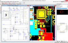
I was able to draw up a bogus 25 part schematic, never using the program before in about 15 minutes! Wires stay connected and auto-route, line weights adjustable, shapes resize nicely, things stay orthogonal, everything one needs. And here's the best part, they've got at least 50 or so tube shapes! Once you go through all their available shape libraries and find them embedded among passive and semiconductor shapes. Even Klystrons, cold cathodes, directly heateds, CRT's, etc. Many tubes. Like a certain shape library, then just assign it to your drawing and done, I assigned all the electronics and radio electronics libraries. Shapes can even be grouped to form complex transformers or switches, or compactrons, the connectors of all the shapes in a group still work, etc.
Also good is that it's a cloud based software so you can use it anytime a computer is near. It costs 9.95 a month.
Just thought I'd mention it, this isn't spamming I don't think, I've done a lot of work in product evaluating for something as seemingly simple as making a tube schematic. So far this wins for me. I know its not Spice and its not a Netlist, but if just nice drawing is all you need I think you'll like this")
(SmartDraw - Create Flowcharts, Floor Plans, and Other Diagrams on Any Device)
I was able to draw up a bogus 25 part schematic, never using the program before in about 15 minutes! Wires stay connected and auto-route, line weights adjustable, shapes resize nicely, things stay orthogonal, everything one needs. And here's the best part, they've got at least 50 or so tube shapes! Once you go through all their available shape libraries and find them embedded among passive and semiconductor shapes. Even Klystrons, cold cathodes, directly heateds, CRT's, etc. Many tubes. Like a certain shape library, then just assign it to your drawing and done, I assigned all the electronics and radio electronics libraries. Shapes can even be grouped to form complex transformers or switches, or compactrons, the connectors of all the shapes in a group still work, etc.
Also good is that it's a cloud based software so you can use it anytime a computer is near. It costs 9.95 a month.
Just thought I'd mention it, this isn't spamming I don't think, I've done a lot of work in product evaluating for something as seemingly simple as making a tube schematic. So far this wins for me. I know its not Spice and its not a Netlist, but if just nice drawing is all you need I think you'll like this
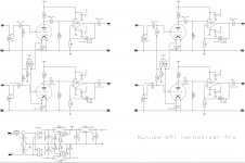
Can you post your drawing?
dave
Sure, later tomorrow I should be able to do that, I haven't tried an export yet and I want to make sure I've gone through all the various versions of tubes to pick out the nicest ones. The drawing I did was just random and bogus. I'm still on the 7 day evaluation, but confident I'll sign up.
Can you post your drawing?
dave
The style looks nice to me..
Attachments

Whoa, Throwback Thursday for me!
I used to use this many many years ago (late nineties, early noughties) for drawing up floorplans. It was "free" back in the day and pretty intuitive / useful. Good to see a software company that has endured.
Not sure I could justify the monthly subs..
I used to use this many many years ago (late nineties, early noughties) for drawing up floorplans. It was "free" back in the day and pretty intuitive / useful. Good to see a software company that has endured.
Not sure I could justify the monthly subs..
Not sure I could justify the monthly subs..
I looked too, and there is a one-off cost option for $287. I don't like the idea of subscriptions on principle, having tried to get out of my '3' telephone contract some years ago ...
I use Scheme It from DigiKey. It works well, and it's free.
Scheme-it | Free Online Schematic and Diagramming Tool | DigiKey Electronics
Scheme-it | Free Online Schematic and Diagramming Tool | DigiKey Electronics
I regret in my enthusiasm I think I spoke too soon here... after using Smartdraw I'm finding that it has some major flaws, the main one being that some shapes will adjust to the line weight command and many other shapes just ignore it. So it's impossible to get everything to have the same line weight if you need that shape. And the other bug is that when some parts connect they are off, like the wire doesn't match the part smoothly. Other bug is that shapes across stencils are based on different scale, so you have to resize too much to get all the shapes of the same relative sizing.
I'm going to keep looking for a diagram tool that can do those beautifully-simple heavy line weight schematic inserts of the Popular Electronics article days. I wonder what John Broskie uses (tubecad.com)?; his diagrams have that heavy weight too.
The Digikey SchemeIt application has the heavy line weight I want, and the parts connect with no jagged offset, but it too has its annoying bugs when you get in trouble on a more complex diagram and have to re-draw it.
I've decided to revisit Visio 2013 it does all the aesthetic things very well, all the shapes honor the line-weight command, etc. but it only comes with 4 vacuum tube shapes. But its extendable with a huge user base. There is a company I found that has for only $35 apparently created Visio 2013 shapes for all the RCA manual receiving tube bases, I'll spring for that package and report back here. Having the option of using generic tube bases with the pins already numbered as well as generic tube symbols would be great.
RF & Electronics Schematic & Block Diagram Symbols for Visio™ -a - RF Cafe
I'm going to Mexico so probably wont get back to this for a few weeks.
- Status
- This old topic is closed. If you want to reopen this topic, contact a moderator using the "Report Post" button.
- Home
- Amplifiers
- Tubes / Valves
- Finally found a schematic drawing tool I like!