Hey everyone,
I like the general build of the Yaqin MC100B, but I am less impressed by its input selector an dvolume pot. Space inside is a bit cramped, so I'm considering turning it in to a power amp.
Since the front input is rated at 0.6V, it appears useful to use this input.
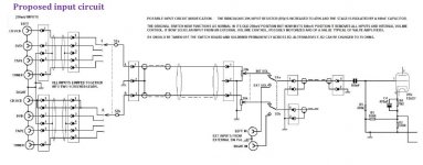
Looking at the schematic, the only thing the switch looks like it's doing is putting R1 (150 Ohm) and R2 (330 Ohm) in parallel over R3 (can't read the value on the schematic 1K2 ?) (bonus question : what is this madness with R1 and R2 ? Why not use a 75 Ohm and be done with it ) (bonus 2 : what is that R5 39K doing there ?)
All that would then remain is simply rip out the volume pots, which for no obvious reason are still active when you use the front inputs.
Or would I be better served by upgrading the volume pot and building a relay input board ? And doing away with that input switch alltogether ? (Incidentally, I don't see the point of it. Any clues anyone ?)
I've considered selling it but there does not seem to be a lot of interest except from lowballers, so I'll keep it.
Thanks,
Pete
I like the general build of the Yaqin MC100B, but I am less impressed by its input selector an dvolume pot. Space inside is a bit cramped, so I'm considering turning it in to a power amp.
Since the front input is rated at 0.6V, it appears useful to use this input.
Looking at the schematic, the only thing the switch looks like it's doing is putting R1 (150 Ohm) and R2 (330 Ohm) in parallel over R3 (can't read the value on the schematic 1K2 ?) (bonus question : what is this madness with R1 and R2 ? Why not use a 75 Ohm and be done with it ) (bonus 2 : what is that R5 39K doing there ?)
All that would then remain is simply rip out the volume pots, which for no obvious reason are still active when you use the front inputs.
Or would I be better served by upgrading the volume pot and building a relay input board ? And doing away with that input switch alltogether ? (Incidentally, I don't see the point of it. Any clues anyone ?)
I've considered selling it but there does not seem to be a lot of interest except from lowballers, so I'll keep it.
Thanks,
Pete
Attachments
Last edited:
R1 and R2 are for magnetic pickup input selection, R5 is for decoupling the HT with C1 in the effort to make it a quieter input stage from hum. Volume controls are always in circuit as without them there is no level setting.
These are very expensive and bought by people who do not realise what they are buying.
These are very expensive and bought by people who do not realise what they are buying.
Get new copy of the schematic pdf from HIFI Engine. I'm able to read it.
When you move S3 between 250 mV. and 600 mV., the GNFB loop is reconfigured. R1 is in parallel with R2 in the 250 mV. position and out of circuit in the 600 mV. position. R3 is 1 Kohm and "sits" between the plate and cathode of the 2 triode "totem pole".
My take from the schematic is that a screw block connector is associated with the I/P of the 'X7. You could hard wire the 600 mV. jack to the screw block and remove R1 to force 600 mV., no matter how S3 is set, and disconnect all the other stuff you dislike too boot. Such a change would be reversible, if a sale surfaces. Use an external control center and avoid fussing with the crowded innards.
BTW, consider increasing R5 to as much as 100 Kohms. Present a light load to whatever is upstream from the modified MC100B.
That 470 Kohm value is way too big. It will interact adversely with the CMiller of the 'X7 triode to form a low pass filter. Loss of high freq. info. is the result.
I said not more than 100 Kohms for R5 for that reason. The 100 nF. (0.1 μF.) cap. is fine, as that value combines with 100 Kohms to form a high pass filter that "corners" at 15.9 Hz. You get some protection against infrasonic noise.
I said not more than 100 Kohms for R5 for that reason. The 100 nF. (0.1 μF.) cap. is fine, as that value combines with 100 Kohms to form a high pass filter that "corners" at 15.9 Hz. You get some protection against infrasonic noise.
- Status
- This old topic is closed. If you want to reopen this topic, contact a moderator using the "Report Post" button.