I decided it would be fun to try some single ended experiments with transmitter triodes. I already had an 811A and 812A from when I was trying some RF stuff. I decided to get an 810 to round out the trio of triodes. I want to use these experiments to learn more about driver stages. So far I've built a few capacitor coupled, no-grid-current amps, so this is new territory for me.
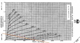
I decided to start with the 810, partly because it's a magnificent looking tube and also because it looks like I could get decent results with zero bias. I can always add some positive bias to increase the power later. I'm attaching the loadline for a 5K OPT (Hammond 1628SEA).
I have a Hammond 126B interstage transformer that I thought I'd try, since from what I'd read it seemed the simplest way to drive grid current. I had already worked with a 12HG7 - with 30mA of plate current it can easily swing 100Vp. I thought that if I coupled it to the 810 with the 126B (5K:5K - max 30mA) I might be successful.
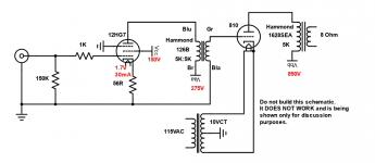
It was not successful (as many of you probably could predict!) and I'm interested to understand what I need to do differently. I'm attaching the schematic.
If I connect a 5K resistor across the IST in place of the 810 I see a nice sine wave. With the 810 in place I get significant distortion. I will post the waveform later when I'm home. As I recall it looks like one half of the wave is distorted. I'm guessing it's the half when grid current is being drawn and my driver is not capable of delivering it. Could it be that the output impedance of the driver is too high?
I'd appreciate any guidance. At some point I will want to look at other drivers including FETs, but for now would like to learn how to use the IST.
Thanks
Richard
I decided to start with the 810, partly because it's a magnificent looking tube and also because it looks like I could get decent results with zero bias. I can always add some positive bias to increase the power later. I'm attaching the loadline for a 5K OPT (Hammond 1628SEA).
I have a Hammond 126B interstage transformer that I thought I'd try, since from what I'd read it seemed the simplest way to drive grid current. I had already worked with a 12HG7 - with 30mA of plate current it can easily swing 100Vp. I thought that if I coupled it to the 810 with the 126B (5K:5K - max 30mA) I might be successful.
It was not successful (as many of you probably could predict!) and I'm interested to understand what I need to do differently. I'm attaching the schematic.
If I connect a 5K resistor across the IST in place of the 810 I see a nice sine wave. With the 810 in place I get significant distortion. I will post the waveform later when I'm home. As I recall it looks like one half of the wave is distorted. I'm guessing it's the half when grid current is being drawn and my driver is not capable of delivering it. Could it be that the output impedance of the driver is too high?
I'd appreciate any guidance. At some point I will want to look at other drivers including FETs, but for now would like to learn how to use the IST.
Thanks
Richard
Attachments
How do you expect to work the final valve?
Take a breath and read a Tube Amplifier book, read it carefully before to use such high voltage (850Volt !), learn how to calculate a simple SE triode amplifier (choosing the Operating Point according to your tube and needs, and correctly polarize the tube in order to properly work first, then refine the calculations in order to get lower
distortions).
http://sportsbil.com/other/Basic Electronics, Volumes 1-5, (1955).pdf
404 Not Found
Building valve amplifiers
: Jones, Morgan (Electronics engineer), author.
: eBook : Toronto Public Library
You cannot learn the basics of vacuum tube electronics from forums, you must read and learn yourself first, and after start building/asking the nice guys on this forum")
Take a breath and read a Tube Amplifier book, read it carefully before to use such high voltage (850Volt !), learn how to calculate a simple SE triode amplifier (choosing the Operating Point according to your tube and needs, and correctly polarize the tube in order to properly work first, then refine the calculations in order to get lower
distortions).
http://sportsbil.com/other/Basic Electronics, Volumes 1-5, (1955).pdf
404 Not Found
Building valve amplifiers
: Jones, Morgan (Electronics engineer), author.
: eBook : Toronto Public Library
You cannot learn the basics of vacuum tube electronics from forums, you must read and learn yourself first, and after start building/asking the nice guys on this forum
Thanks for your response. I have a copy and have read quite a bit of Morgan's book. I have built a number of audio tube amps and also an RF amp running at 850V. Which part of Morgan's book do you suggest I read for using ISTs to drive a positive grid current tube? I couldn't find much. Perhaps you could point me to any material on this? I've done quite a bit of searching without much luck.How do you expect to work the final valve?
Take a breath and read a Tube Amplifier book, read it carefully before to use such high voltage (850Volt !), learn how to calculate a simple SE triode amplifier (choosing the Operating Point according to your tube and needs, and correctly polarize the tube in order to properly work first, then refine the calculations in order to get lower
distortions).
http://sportsbil.com/other/Basic%20Electronics,%20Volumes%201-5,%20(1955).pdf
404 Not Found
Building valve amplifiers
: Jones, Morgan (Electronics engineer), author.
: eBook : Toronto Public Library
You cannot learn the basics of vacuum tube electronics from forums, you must read and learn yourself first, and after start building/asking the nice guys on this forum
The OP I have chosen for the 810 is on the loadline that I posted. At 850V and a grounded grid I get a plate current of about 85mA.
Thanks
Richard
Last edited:
Based on the graph I attached, -50V would be well below cutoff for the tube. 850V on the plate with 0V on the grid gives about 85mA of plate current and is below the max plate dissipation (125W) for the tube. Am I missing something?I would expect the grid to be biased negative say -50V not at 0V. That normally results in heavy conduction.
Richard
If you use a pentode driver, the plate resistance, rp, is very high.
Now, you use that pentode to drive a very non-linear impedance load.
The pentode driver and interstage transformer will drive the output tube both positive and negative.
1. When the output tube grid goes positive, it conducts, it might be around 1k Ohm.
Your pentode driver high impedance plate is trying to drive that (not good).
2. When the output tube grid goes negative, it is a very high impedance.
Your pentode driver high impedance plate drives the high impedance output tube grid, it likes that grid impedance.
But there is a secondary effect, the pentode is also trying to drive the interstage transformer.
At low frequencies, the inductive reactance of the interstage has a low impedance.
And and high frequencies, the distributed capacitive reactance of the interstage has a medium to low impedance. At mid frequencies, the interstage load is better for the pentode.
Last edited:
Thanks - this is very helpful. I was concerned about the output impedance of the driver being too high. According to the graph on the gird (attached) at +60V the grid current is around 20mA. Does that give a load of 60/0.02 = 3KOhm? Not sure if I got that calculation right.
On the frequency impact on the interstage - is that a general problem with ISTs or is it pentode-specific?
I can see that a cathode follower can be used to lower output impedance - do I need a buffer stage?
Thanks for your help,
Richard

On the frequency impact on the interstage - is that a general problem with ISTs or is it pentode-specific?
I can see that a cathode follower can be used to lower output impedance - do I need a buffer stage?
Thanks for your help,
Richard
Last edited:
The 810 is a bit of a pain to build with, but it's doable. I have 810 amps sitting in my house that make 50W, but it took a lot of work.
The first recommendation I would have is to look at your 5K load line and move your operating point to the midway point between where it hits the X axis and where it hits the VG=VP. That will be more like 675V. If your OT can't handle the idle current there, then adjust the operating point so that you are about in the middle of the load line at your quiescent operating point, otherwise you're throwing away power.
My second recommendation would be to consider that the Rp of the 810 will be somewhere around 10K, and your output transformer is a 5K unit. You have to use feedback to reconcile these issues. I used local Schade feedback to account for that. Your load line it totally reasonable though, don't sweat that.
Lastly, yes, the grid is going to draw current. No, the 5K:5K interstage transformer is not adequate for what's going on. Pretend the grid of the 810 is a 600 ohm resistor in terms of AC analysis and work from there. A 12HG7 would be a fine tube choice to wire up as a cathode follower to directly couple to the 810 grid, though you'd probably want two to deal with the peak current required.
This will leave you needing a third stage. I used a pentode up front because it was the most sensible choice for Schade feedback. There are other ways to skin that cat, and that might not be what you're after, but you'll still want to have a 3 stage amp.
(The 1642SE will also be calling your name, I've really been hoping to find someone local to me who has one that I can measure)
The grid current curves you provided will help you.
Take the slope of a curve, say the +40V grid curve.
With the plate at 200V, the slope of the grid current is almost flat.
With the plate at 100V, the slope of the grid current near that point is about:
100V +/- 10 V (20V change), the current changes about +/- 5 mA (10 mA change).
20V / 0.01A = 2000 Ohms.
The grid impedance with the grid at +40V, and the plate at 100V (impedance at audio, not RF) is about 2000 Ohms.
Yes, you need a lower impedance driver, and perhaps some negative feedback for the driver.
A properly designed cathode follower can have low impedance, and lots of current, and is a form of negative feedback (degeneration).
But there are lots of factors to design a cathode follower to properly drive such a non-linear load impedance.
Some power triodes can drive fairly low load impedance.
But you probably will need negative feedback here too.
But notice the large changes of output tube grid current when the grid voltage is 20V, 40V, and 60V, even when the plate voltage swings to 400V with signal applied (half of your 800V B+).
Problems to solve.
Understand, the 810 triode was intended to be used either as a push pull class B audio amp (AM modulator service), or as a class C RF amplifier (class C is extremely non linear, almost a 'switch' from full on to cut off, and nothing in between).
You are attempting to use it as a class A single ended audio amplifier.
Pretty looks, but very hard to use that way.
Last edited:

This is great. Thanks.The 810 is a bit of a pain to build with, but it's doable. I have 810 amps sitting in my house that make 50W, but it took a lot of work.
The first recommendation I would have is to look at your 5K load line and move your operating point to the midway point between where it hits the X axis and where it hits the VG=VP. That will be more like 675V. If your OT can't handle the idle current there, then adjust the operating point so that you are about in the middle of the load line at your quiescent operating point, otherwise you're throwing away power.
My second recommendation would be to consider that the Rp of the 810 will be somewhere around 10K, and your output transformer is a 5K unit. You have to use feedback to reconcile these issues. I used local Schade feedback to account for that. Your load line it totally reasonable though, don't sweat that.
Lastly, yes, the grid is going to draw current. No, the 5K:5K interstage transformer is not adequate for what's going on. Pretend the grid of the 810 is a 600 ohm resistor in terms of AC analysis and work from there. A 12HG7 would be a fine tube choice to wire up as a cathode follower to directly couple to the 810 grid, though you'd probably want two to deal with the peak current required.
This will leave you needing a third stage. I used a pentode up front because it was the most sensible choice for Schade feedback. There are other ways to skin that cat, and that might not be what you're after, but you'll still want to have a 3 stage amp.
(The 1642SE will also be calling your name, I've really been hoping to find someone local to me who has one that I can measure)
I'm attaching a revised OP. I assume that's because it offers maximum voltage swing for maximum power output? The reason I picked the OP I did was that it was zero bias and saved me the step of building a bias supply. I figured I could add that in later and move the OP once I got it working at lower power. The new OP requires just under +20V bias and would result in a plate current of 120mA - the max the 1628SEA can handle. It does look like a good place to end up. It could deliver 30W there.
I looked at a 10K loadline too - the 1628SEA has a 16Ohm tap - if I connected an 8Ohm load to that I assume the 810 would see a 10K load? Would that compromise the sound quality too much?
So, if I want to use an IST I need to get a different one - maybe one that steps down? I like the idea of using the 12HG7 as a cathode follower - if my IST isn't going to work then I might move in that direction. For the first stage could I use a triode like the 5687 or 6SN7? I have plenty of those.
Yes the 1642SE would be the thing to get. My power supply uses the Hammond 720 that can deliver 300mA. Maybe at some point.
Thanks
Richard
You don't need a bias supply. Use a choke loaded cathode follower. The Hammond 155C and 156C are good for this purpose. You'll notice that the 8mA DC rating of the 156C and it's 3.7K DCR make a voltage drop of 30V while the 155C is 22V. Your desired quiescent grid bias voltage is about 18V DC, so either choke won't have a problem with that. I will design the cathode follower so that a little positive bias should be applied to its grid in order for it to draw sufficient current to bias the output tube to the desired current. Just keep in mind that both the choke and the 810 grid are DC current paths.
You do not want to adjust the ratios of a series feed output transformer, especially not a Hammond! Even if you do, the damping problem is still there.
Yes, the IST is not well suited for this project IMO.
What you use up front is up to you. That is the toughest part of designing an amp like this. You can just use something with tons of gain up front and put feedback around the whole amp, as the bandwidth of the output transformer isn't sufficient to avoid oscillation issues.
If you have the cathode follower driver grid at a positive voltage versus its cathode, again, you have to deal with that low impedance grid too, not just the low impedance grid of the output tube.
Another non-linear loading grid to deal with.
If we say, for example, that the cathode follower with 0V DC on the grid directly coupled to the 810 grid with a Hammond 165C as an additional load will only draw enough current to bring the bias voltage to +15V, we can apply a little positive bias voltage to the grid of the cathode follower to entice it to draw a bit more current to increase the bias voltage available to the 810.
This does not change the input impedance of the cathode follower provided the positive grid bias doesn't get too close to the cathode voltage of the cathode follower.
I will typically use a 25K/2W pot with one end attached to ground, the wiper connected to the grid leak at the cathode follower, then the other end connects to B+ through a high value resistor to set a reasonable range of bias.
That makes sense, it's a slope and not a horizontal line.The grid current curves you provided will help you.
Take the slope of a curve, say the +40V grid curve.
With the plate at 200V, the slope of the grid current is almost flat.
With the plate at 100V, the slope of the grid current near that point is about:
100V +/- 10 V (20V change), the current changes about +/- 5 mA (10 mA change).
20V / 0.01A = 2000 Ohms.
The grid impedance with the grid at +40V, and the plate at 100V (impedance at audio, not RF) is about 2000 Ohms.
I am up for a challenge - experimenting and learning is my objective. I already have tube amps that I listen to.Yes, you need a lower impedance driver, and perhaps some negative feedback for the driver.
A properly designed cathode follower can have low impedance, and lots of current, and is a form of negative feedback (degeneration).
But there are lots of factors to design a cathode follower to properly drive such a non-linear load impedance.
Some power triodes can drive fairly low load impedance.
But you probably will need negative feedback here too.
But notice the large changes of output tube grid current when the grid voltage is 20V, 40V, and 60V, even when the plate voltage swings to 400V with signal applied (half of your 800V B+).
Problems to solve.
I also have an 812A to experiment with that looks like it might be similarly challenging (if not as good lookingUnderstand, the 810 triode was intended to be used either as a push pull class B audio amp (AM modulator service), or as a class C RF amplifier (class C is extremely non linear, almost a 'switch' from full on to cut off, and nothing in between).
You are attempting to use it as a class A single ended audio amplifier.
Pretty looks, but very hard to use that way.
).Thanks
Richard
Class A2 is fun to mess with. It's worth the investment in figuring out how to build A2 amps in a way that works for you.
The design challenges that you would face with the 810 would be identical with the 812.
(Also if you need advice on a filament supply for the 810, I can help there too)
The design challenges that you would face with the 810 would be identical with the 812.
(Also if you need advice on a filament supply for the 810, I can help there too)
Thanks - this is getting very interesting for me. I went back a re-read Morgan Jones's chapter on the cathode follower, now that I know why I want one. It all makes sense except for one thing. He says that the gain of the cathode follower is just less that unity. I assume that means that to be able to swing 60 Vp out the tube will need to handle a 60 Vp on the grid. That rules out most of the driver tubes I can think of. Does that mean I have to use a power tube that needs that kind of grid voltage? If so, I have a 2A3 amp that I have been playing with - I was thinking I could change the 2A3 into a cathode follower as an experiment. But then the chokes you mentioned have an 8mA limit and the 2A3 needs 60mA to operate. Where do I find a tube that can do all this with only an 8mA plate current? I think I must be missing part of the puzzle.You don't need a bias supply. Use a choke loaded cathode follower. The Hammond 155C and 156C are good for this purpose. You'll notice that the 8mA DC rating of the 156C and it's 3.7K DCR make a voltage drop of 30V while the 155C is 22V. Your desired quiescent grid bias voltage is about 18V DC, so either choke won't have a problem with that. I will design the cathode follower so that a little positive bias should be applied to its grid in order for it to draw sufficient current to bias the output tube to the desired current. Just keep in mind that both the choke and the 810 grid are DC current paths.
You do not want to adjust the ratios of a series feed output transformer, especially not a Hammond! Even if you do, the damping problem is still there.
Yes, the IST is not well suited for this project IMO.
What you use up front is up to you. That is the toughest part of designing an amp like this. You can just use something with tons of gain up front and put feedback around the whole amp, as the bandwidth of the output transformer isn't sufficient to avoid oscillation issues.
Thanks
Richard
Yes - I'm enjoying the journey - thanks! Right now I'm just using a center tapped transformer for the filament, since I had decent results with that approach for the 2A3. Once I get to the stage of worrying about hum I may well be looking for suggestions.Class A2 is fun to mess with. It's worth the investment in figuring out how to build A2 amps in a way that works for you.
The design challenges that you would face with the 810 would be identical with the 812.
(Also if you need advice on a filament supply for the 810, I can help there too)
Richard
Is that where feedback comes in?If you have the cathode follower driver grid at a positive voltage versus its cathode, again, you have to deal with that low impedance grid too, not just the low impedance grid of the output tube.
Another non-linear loading grid to deal with.
Richard
- Status
- This old topic is closed. If you want to reopen this topic, contact a moderator using the "Report Post" button.
- Home
- Amplifiers
- Tubes / Valves
- Driver for 810 SE