Change your scope sampling rate / time base to take the spectrum to 50kHz or 100kHz.
See if the offending tone remains at 20kHz, or if it is just a foldover of a frequency that is more than 2X the sampling rate.
A foldover frequency will either appear to change frequency, or disappear completely when you raise the sampling rate.
Also, you have inductance and capacitance at the input, negative feedback, and capacitance and inductance at the output.
There is phase shift in that circuit.
Looks like a possible oscillator to me.
Fed-back filter circuits are tricky.
They can work with just one triode.
But a different network and circuit with 2 triodes may be less prone to oscillate.
Last edited:
Problem solved!
For each filter section the RC filter components are on a little plug-in module.
I took the 14kHz high pass module and plugged it into the 35Hz low pass filter board.
Result was that the 50Hz and 100Hz noise was significantly reduced.
The only difference was the size of the output capacitor with the 35Hz low pass filter having a 10uF output capacitor.
I plugged the 14kHz module back into the 14kHz filter board and soldered a 1uF capacitor across the existing 8.1nF capacitor. Same result.
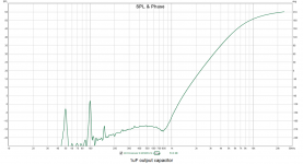
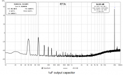
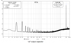
According to the REW RTA plot the 100Hz is now 65dB below the 20kHz test tone and the 50Hz lower still.
Now I just need to see what's the lowest value of output capacitor I can get away with.
Trying a much larger capacitor was indeed the solution.
I thought I solved the problem myself but the solution was a few posts back!... try a much larger cap there - your cathode follower output is a low impedance to AC ground a very small cap makes it a very high impedance at low frequencies.
For each filter section the RC filter components are on a little plug-in module.
I took the 14kHz high pass module and plugged it into the 35Hz low pass filter board.
Result was that the 50Hz and 100Hz noise was significantly reduced.
The only difference was the size of the output capacitor with the 35Hz low pass filter having a 10uF output capacitor.
I plugged the 14kHz module back into the 14kHz filter board and soldered a 1uF capacitor across the existing 8.1nF capacitor. Same result.


According to the REW RTA plot the 100Hz is now 65dB below the 20kHz test tone and the 50Hz lower still.
Now I just need to see what's the lowest value of output capacitor I can get away with.
Trying a much larger capacitor was indeed the solution.
The filtering is done by the filter, the output capacitor doesn’t - or shouldn’t (thats bad design) contribute. The bigger your output capacitor is the smaller it’s resistance at low frequencies and thus the better it is at shorting out low frequency interference.
Yes. Noise deteriorates significantly with 0.1uF and is even better still with 10uF.
Must be. Despite the "Internal electrostatic shields to maximise output balance and noise immunity."That I think means its the output transformer that's picking up the hum.
As you don't need the frequency response at LF I wander if you could use something with less inductance/turns, say and isolation transformer. I guess you need the balanced output. Pleased you are getting to the bottom of it, something through must be generating the field. Do you have a power supply choke?
I wonder if you could use something with less inductance/turns, say and isolation transformer. I guess you need the balanced output.
I don't think I could persuade the person I'm rebuilding the crossovers for to swap out the Sowter output transformers. They are a problem though because the Type 8940s have a 3:1 turns ratio causing a 9dB signal loss.
Last edited:
Do you have a power supply choke?
I don’t think I have any spare ones. What for? Filter the output?
Nop just wondered if that was radiating.
There's a 15H choke right under the filter board in the power supply chassis.
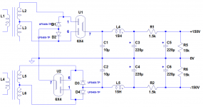
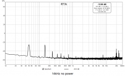
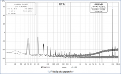
I've attached spectra with power off and power on.
Most of the 50Hz is environmental. 10dB to 15dB is contributed by the power supply.
All of the 100Hz is contributed by the power supply. 40dB or so.
150Hz is the same. 200Hz is the power supply.
I wondered if that was generating the magnetic field - its should not as its just passing a constant DC current. I just wondered if you could move it out of the way just to test. The line output transformers are a bit 'old school'. There's a lot of stuff which is much better screened against magnetic interference. You do need the turns ratio as the 12ax7 will have trouble driving a 600R load at line level directly.
Last edited:
What a difference!
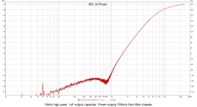
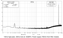
Moving the PSU chassis out from under and 700mm way (the length of the umbilicals) made a HUGE difference!
Can you point me to something? Jensen JT-11-EMCF?
The 12AT7s I have on order should be more capable of driving 600R.
I just wondered if you could move it out of the way just to test.
Moving the PSU chassis out from under and 700mm way (the length of the umbilicals) made a HUGE difference!


The line output transformers are a bit 'old school'. There's a lot of stuff which is much better screened against magnetic interference.
Can you point me to something? Jensen JT-11-EMCF?
You do need the turns ratio as the 12ax7 will have trouble driving a 600R load at line level directly.
The 12AT7s I have on order should be more capable of driving 600R.
I'am no expert on transformers - but there are plenty of others on diyaudio who can help you. To work out turns ratio whats the maximum output level you wish to drive and into 600R or open. I guess you want something with a magnetic screen. Changing to toroids in the power supply will help too.
Having a quick look hammond do a few
https://www.hammfg.com/electronics/transformers/audio/560.pdf
Some have humbucking construction, others have a mu metal shield. We used to use some round ones when I was in radio.
https://www.hammfg.com/electronics/transformers/audio/560.pdf
Some have humbucking construction, others have a mu metal shield. We used to use some round ones when I was in radio.
Having a quick look hammond do a few
https://www.hammfg.com/electronics/transformers/audio/560.pdf
Some have humbucking construction, others have a mu metal shield. We used to use some round ones when I was in radio.
Thanks!
Earthing with separate filter and power supply chassis and balanced IO
[SIZE=-1]Should the HT 0V be connected to the chassis or be floating in these crossovers?[/SIZE][SIZE=-1]
[/SIZE]
[SIZE=-1]Is it irrelevant because they have balanced inputs and outputs?[/SIZE][SIZE=-1]
[/SIZE]
[SIZE=-1]I currently have the HT 0V connected to the mains earth/chassis in the power supply box. [/SIZE][SIZE=-1]
[/SIZE]
[SIZE=-1]I run OV through a cable in each of the 2 umbilicals along with the ±150V to the filter boxes where each of those cables is also connected to the chassis.[/SIZE][SIZE=-1]
[/SIZE]
[SIZE=-1]The alternative would be to leave the HT 0V floating and run a separate chassis earth through each of the umbilicals (Morgan Jones says you should run more than one for safety).[/SIZE]
I think as you have balanced inputs and outputs 0V and chassis can be the same thing. Definitely not floating as you can build up quite a hefty charge. I sometimes connect the two with 10r and 47nf. In your case run both 0v and chassis ground up the cable, they are then separate on the filter boxes (if you need to earth these). Only connect them together at the power supply in one place and not where the rectifier currents flow back to the mains transformer.
Last edited:
- Status
- This old topic is closed. If you want to reopen this topic, contact a moderator using the "Report Post" button.
- Home
- Amplifiers
- Tubes / Valves
- Crossover filter noise problem