Hi.
I’m modifying a 4-way crossover. Left and right filter boxes and left and right power supplies.
I’m having a low frequency noise problem with the 14kHz high pass crossover filter in one of the boxes.
Here’s the schematic:

The output transformers are Sowter Type 8940s.
Amplitude vs frequency for the “good” filter looks like this:

100Hz is concerning but is 50dB down. When I’ve measured it at other times it has looked somewhat better than that.
The bad one looks like this:

100Hz is less than 30dB down and the hum is easily audible in a little full range test speaker.
With the output taken from the cathode of the cathode follower, amplitude vs frequency looks like this:

So 50Hz, 100Hz and harmonics seem to be getting in after the output capacitor.
On the oscilloscope at 10mV/division there’s a lot of high frequency hash on the ±150V rails but no 50Hz or 100Hz. They're heavily filtered with CLCRC in the power supply box plus another 220uF and multiple .22uF capacitors in the filter box.
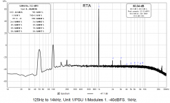
The other 3 filter sections in the unit are fine. Here’s the 125Hz to 14kHz for example:

I’ve tried switching tubes but that made no difference.
I’ve also tried various earthing arrangements around the output transformer but again, no difference.
So, any suggestions please?
I’m modifying a 4-way crossover. Left and right filter boxes and left and right power supplies.
I’m having a low frequency noise problem with the 14kHz high pass crossover filter in one of the boxes.
Here’s the schematic:
The output transformers are Sowter Type 8940s.
Amplitude vs frequency for the “good” filter looks like this:
100Hz is concerning but is 50dB down. When I’ve measured it at other times it has looked somewhat better than that.
The bad one looks like this:
100Hz is less than 30dB down and the hum is easily audible in a little full range test speaker.
With the output taken from the cathode of the cathode follower, amplitude vs frequency looks like this:
So 50Hz, 100Hz and harmonics seem to be getting in after the output capacitor.
On the oscilloscope at 10mV/division there’s a lot of high frequency hash on the ±150V rails but no 50Hz or 100Hz. They're heavily filtered with CLCRC in the power supply box plus another 220uF and multiple .22uF capacitors in the filter box.
The other 3 filter sections in the unit are fine. Here’s the 125Hz to 14kHz for example:
I’ve tried switching tubes but that made no difference.
I’ve also tried various earthing arrangements around the output transformer but again, no difference.
So, any suggestions please?
I would look at the power supply and grounding. The high harmonics x100Hz look like rectifier currents. Check you are taking the return current from the rectifiers back to the mains transformer directly not through the signal path. A schematic of the power supply would be useful.
On another suggesting I would bring down the impedance of the filter C2,C3,C4. Does R4 have to be so big. The node around R4 will be very sensitive to pickup and heater ac.
Maybe.
R1 = 36kΩ
R3 = 15kΩ
R4 = 270kΩ
C2 = 220pF
C3 = 220pF
C4 = 220pF
Another suggestion is to use a LC filter so that the input grid has a shunt inductor to ground.
Maybe use other half of 12ax7 as input buffer from transformer so input does not affect response.
I would include resistor in series with C6 to prevent oscillation, if you want line levels a 12at7 with more current. Hope I've not made too many suggestions.
Last edited:
Thanks for your suggestions. Here's the power supply:

I need to draw up the schematic for the heater supply. It appears to have some sort of 2N3055-based regulator in it. I've never actually looked at 126V heater supplies on a scope.
The power supplies are in separate boxes. 0V, ±150V and separate 0V/ 12.6VDC (floating with artificial centre tap in the power supply box) is supplied to the filter boxes via umbilicals.
There are 220uF capacitors on the ±150V and 10,000uF on the 12.6VDC on entry to the filter boxes.
Each filter section has its own PCB. 0V ±150V and heater floating 0V/12.6V are supplied to each card.
0V is taken from the card with the signal to the output capacitor and output transformer.
On another suggesting I would bring down the impedance of the filter C2,C3,C4. Does R4 have to be so big. The node around R4 will be very sensitive to pickup and heater ac.
Maybe.
R1 = 36kΩ
R3 = 15kΩ
R4 = 270kΩ
C2 = 220pF
C3 = 220pF
C4 = 220pF
Another suggestion is to use a LC filter so that the input grid has a shunt inductor to ground.
Maybe use other half of 12ax7 as input buffer from transformer so input does not affect response.
I would include resistor in series with C6 to prevent oscillation, if you want line levels a 12at7 with more current. Hope I've not made too many suggestions.
Thanks. Great advice! I actually have 12AT7s on order. Should arrive any day.
The first capacitor in the power supply is very low.
I would have expected at least 22uf or 47uf.
But I suspect with the 220uf's it probably wont make much difference.
As someone else said your crossover caps are very small making the circuit very high impedance and that will pick up noise easier.
I would have expected at least 22uf or 47uf.
But I suspect with the 220uf's it probably wont make much difference.
As someone else said your crossover caps are very small making the circuit very high impedance and that will pick up noise easier.
Last edited:
Thanks. Great advice! I actually have 12AT7s on order. Should arrive any day.
I have found the 12AX7 to be a noisy little blighter, partly because of high gain.
I have a couple of times moved to the 12AU7 for lower gain and noise.
Some people will rubbish the 12AU7 but I have had good results with it.
The first capacitor in the power supply is very low. I would have expected at least 22uf or 47uf.
Thanks for spotting that. They're actually 10uF. The 0.01uF ones were from an earlier iteration when I was converting the power supply from +250V to ±150V.
I restored the original 10uF capacitors to get the voltage up to ±150V.

Just check you are taking the chassis ground from C5/C6 not the transformer end in case you have created a current loop through the chassis to the input - I don't see how you can however. The choice of valve does not make that much difference to gain in a cathode follower. A 12at7 or 12au7 allows you to increase output drive. The heater could be an issue. With only 56p on grid and a 1meg id won't take much cap coupling to get pickup of any wiring or the valve itself. Do you have a time domain waveform of the buzz - it may help to see what it is?
Last edited:
Do you have a time domain waveform of the buzz - it may help to see what it is?
Here you go. Also a 20kHz THD+N plot.


The HF noise is present even with the crossover switched off. I can't see any 100Hz on the rails.
High Frequency Noise . . .
My first guess is you have a ground loop.
Your Rigol scope has a (high frequency)switcher power supply.
There is an EMI loop from the scope power mains cord to the amplifier power mains cord and back to the scope probe ground clip.
Yes?
Coax and shielded cables have a factor called reverse transfer impedance.
They are not perfect, and the ground currents induce a signal into the center conductor.
"Grounds are Commonly Misunderstood".
And any amplifier that has a high frequency switching power supply might be able to do the same, during a similar scope measurement setup,
even if the scope has a linear power supply.
There is a Radiated side of EMI testing of products to meet regulations.
There is also a Conducted side of EMI testing of products to meet regulations. Conducted EMI is the trouble that is causing the noise.
Just because two products meet EMI regulations is not a guarantee that they are EMC.
Electro Magnetic Interference.
Electro Magnetic Compatability
Last edited:
Yes I think your ground on scope probe is missing or your not connected to signal ground!
The 20KHz tone is from your sig gen?
The LF waveform does not look like a rectifier current, it's quite triangular mainly 100Hz but some 50Hz so that looks more like filtered DC from the supply.
Try shorting out R4 see if it goes.
The 20KHz tone is from your sig gen?
The LF waveform does not look like a rectifier current, it's quite triangular mainly 100Hz but some 50Hz so that looks more like filtered DC from the supply.
Try shorting out R4 see if it goes.
Last edited:
HF noise and ground loop
Thanks for the reply. The Rigol does indeed have a switching power supply. My computer tower is close but I turned that off and it didn't make a difference.
The HF noise was significantly reduced if I unplug the input from, and output to my Pete Millett soundcard interface. Sounds like those cables (twin-core shielded microphone cable) could be picking up the HF switching noise.
The power supply ±150V earth is connected to the star ground/mains earth in the power supply chassis and also in the filter chassis.
I did some tests with an amp and a cheap full range speaker and this 14kHz high pass filter was the only one with noticeable hum.
Given the input from my Pete Millett soundcard interface is floating single-ended and the output to my Pete Millett soundcard interface is balanced it's hard to see where I might be getting a ground loop from.
High Frequency Noise . . .
My first guess is you have a ground loop.
Your Rigol scope has a (high frequency)switcher power supply.
There is an EMI loop from the scope power mains cord to the amplifier power mains cord and back to the scope probe ground clip.
Yes?
Thanks for the reply. The Rigol does indeed have a switching power supply. My computer tower is close but I turned that off and it didn't make a difference.
The HF noise was significantly reduced if I unplug the input from, and output to my Pete Millett soundcard interface. Sounds like those cables (twin-core shielded microphone cable) could be picking up the HF switching noise.
The power supply ±150V earth is connected to the star ground/mains earth in the power supply chassis and also in the filter chassis.
I did some tests with an amp and a cheap full range speaker and this 14kHz high pass filter was the only one with noticeable hum.
Given the input from my Pete Millett soundcard interface is floating single-ended and the output to my Pete Millett soundcard interface is balanced it's hard to see where I might be getting a ground loop from.
Yes I think your ground on scope probe is missing or your not connected to signal ground!
The 20KHz tone is from your sig gen?
The LF waveform does not look like a rectifier current, it's quite triangular mainly 100Hz but some 50Hz so that looks more like filtered DC from the supply.
Try shorting out R4 see if it goes.
Scope probe is indeed connected to ground. Tried a different probe just to be sure.
The 20kHz is out of my computer soundcard via Pete Millett's soundcard interface.
If none of this works I'll add some Maida regulators. Before I re-built the units they were in service for many years without though.
I've ordered some 220p capacitors and I'll try shorting R4 tomorrow.
Your measurements indicate the hum is getting in after the cathode follower. Is C6 really 81pF? If so try a much larger cap there - your cathode follower output is a low impedance to AC ground a very small cap makes it a very high impedance at low frequencies. Failing that is your output transformer picking up the hum?
Yep shorting R4 will give a good clue as to whether is getting into the grid directly.
Shorted R4 and also tried 100k in parallel with the existing 1M.
Unfortunately the problem still remained.
Here are 20kHz real-time analysis with R4 shorted and amplitude vs frequency with R4 100k||1M.


Be a while before I get the 12AT7s I've ordered to see if they make any difference.
Your measurements indicate the hum is getting in after the cathode follower. Is C6 really 81pF? If so try a much larger cap there - your cathode follower output is a low impedance to AC ground a very small cap makes it a very high impedance at low frequencies. Failing that is your output transformer picking up the hum?
Thanks for this. So, the 81p is actually 8.1n.
The guy who built these crossovers had a habit of hiding all the capacitor values. He did it with all the resistors too - red things with values printed on them. Not sure where I got 81p from. Might be from putting a capacitance meter across the capacitor in situ and misreading the display.
I removed the capacitor to try a different value and was finally able to see the values of the 2 paralleled polystyrene caps.
Excellent suggestion about the output transformer. Unfortunately I've already tried routing the output of this 14kHz high pass board through the adjacent 125Hz to 14kHz band pass transformer. The problem was still there.
Here's the corrected schematic also showing the extent of the filter module and the filter board.

- Status
- This old topic is closed. If you want to reopen this topic, contact a moderator using the "Report Post" button.
- Home
- Amplifiers
- Tubes / Valves
- Crossover filter noise problem