Why not take the 2 tubestage phonostage to the next level. See diagram below.
Less hiss and distorsion. With standard values in riaa filter.
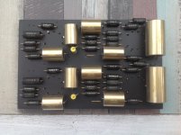
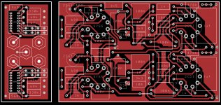
Be sure i will this designed a pcb for this, i like mu follower stages; high gain, low output impedance, low non-linear distortion
Attachments
Last edited:
replace the valve follower with a bipolar transistor stage.Much better results! 20khz squarewave perfect reproduction, no noise.Why not take the 2 tubestage phonostage to the next level. See diagram below.
Less hiss and distorsion. With standard values in riaa filter.
https://www.diyaudio.com/forums/analogue-source/255149-unu-pnono-riaa-mm-preamp.html#post5485527
Actually 25khz square wave before slew rate limiting.That meant also 480khz sine wave perfect reproduction before visible deformation on scope...I dont like to listen to 20khz square waves.")
loading resistor before or after filter network?
It baffles me too. I don't understand why so many circuits do that by creating an unnecessary voltage divider and reducing gain. Plus, placing the loading resistor in front of the filter network makes the math easier too. I would like to hear the reasoning behind it though.
I think puting R5 in front of the filter gives more gain.
And here the same mistake to put R11 after the filter.Gives a unwanted devider R1-R11. With R11 in front of the filter, before R1, one gets extra free gain.
It baffles me too. I don't understand why so many circuits do that by creating an unnecessary voltage divider and reducing gain. Plus, placing the loading resistor in front of the filter network makes the math easier too. I would like to hear the reasoning behind it though.
A square wave applied into an RIAA compensated preamp will Not be a square wave at the preamp output.
You first have to apply the square wave into the Inverse RIAA compensation network; then apply that output to the RIAA preamp input; and then you may, or you may not, get a square wave out of the preamp.
How many test records have a 20kHz square wave test signal?
The first part of that square wave signal other than the 20kHz fundamental is the third harmonic (60kHz).
And the next components of that same square wave are the 5th harmonic (100kHz), and 7th harmonic (140kHz).
What kind of test record does that?
What kind of phono cartridge does that?
Perfect 20kHz square wave from an RIAA device indeed!
Where is the need for that?
There is nothing like the results of stripping out the innermost layer of the onion, unless you first remove the dirt from the outer layer of that same onion.
Yes?
I do not agree completely.
The most useful feature of square wave phono amp testing is
that it is a very good and quick measure of RIAA precision.
Another feature is that phase aberrations are easily detected
which do not show up in the frequency response alone.
Clipping behaviour is easily checked with square waves and
the differences in active and passive RIAA correction etc are
clearly visible.
and quick design and production testing square waves of
0.1, 1 and 10kHz are sufficient.
I think many readers here know this.A square wave applied into an RIAA compensated preamp will Not be a square wave at the preamp output.
You first have to apply the square wave into the Inverse RIAA compensation network; then apply that output to the RIAA preamp input; and then you may, or you may not, get a square wave out of the preamp.
The most useful feature of square wave phono amp testing is
that it is a very good and quick measure of RIAA precision.
Another feature is that phase aberrations are easily detected
which do not show up in the frequency response alone.
Clipping behaviour is easily checked with square waves and
the differences in active and passive RIAA correction etc are
clearly visible.
A phono stage will not be developed and tested with test records.How many test records have a 20kHz square wave test signal?
CD-4 pick ups have a response beyond 40 kHz.What kind of phono cartridge does that?
The term perfect is not adequate in this context. For repairPerfect 20kHz square wave from an RIAA device indeed!
and quick design and production testing square waves of
0.1, 1 and 10kHz are sufficient.
Before i have used bipolar transistors for the mu-follower i had used 2x E282F in parallel and i had 10khz perfect square wave.Some might not believe , but extending that response to 20khz square wave gave me a better, clearer sound , although i don't hear anything over 14khz...Unfortunately all the measurement pictures were deleted by Tinypic this summer...I do not agree completely.
The term perfect is not adequate in this context. For repair
and quick design and production testing square waves of
0.1, 1 and 10kHz are sufficient.
...phase aberrations are easily detected
which do not show up in the frequency response alone...
If the frequency response is correct, the phase is correct.
(Assuming you have not hidden a pure delay in there, a tape or BBD.)
Many readers know about these subjects.
(But many readers do not).
Phase is an easy test if you have a sine wave oscillator and an XY scope.
A little time, a little patience, a little work, and you get the results.
But just be sure the phase of your reverse RIAA network is correct, including when it drives the preamp input stage, including the grid resistor, and especially the Miller Effect input capacitance of the input stage (and the varying gain of the input stage plate if it is driving anything other than a constant impedance across the frequency band). Any change of the plate load versus frequency will cause the gain to change, and consequently the
Miller Effect capacitance reflected back to the input will not be a constant either.
And remember, different cartridges have different DCR, different inductance, and the tonearm cable and coax from there to the preamp have many different possible capacitances.
Does anybody remember the Saddle-Back frequency response curve of the beloved Shure V15 cartridge?
Track-ability, Yes.
Flat frequency response, No.
Onion Layers indeed.
Last edited:
hello again,
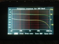
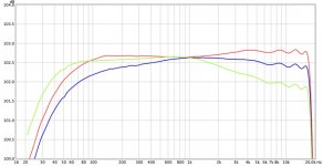
today i finally finished the preamplifier. In the picture you can see 3 frequency responses using different riaa filters. Which of them do you believe will sound better?
The green response is the riaa filter from the elektor magazine , the blue one is the groovewatt tube preamp, and the red one is the groovewatt preamplifier but with the resistor in series with capacitor changed to a smaller one (from 10,8K to 10,14K).(I know that the differences are small)
can you suggest a change so it can be <flatter> ?
Attachments
Last edited:
hello again,
today i finally finished the preamplifier. In the picture you can see 3 frequency responses using different riaa filters. Which of them do you believe will sound better?
The green response is the riaa filter from the elektor magazine , the blue one is the groovewatt tube preamp, and the red one is the groovewatt preamplifier but with the resistor in series with capacitor changed to a smaller one (from 10,8K to 10,14K).(I know that the differences are small)
can you suggest a change so it can be <flatter> ?
I think nobody can tell you which will sound better. There are much more parameters that have influence on the soundsignature. Things like phase shift, distorsion, slewrate etc. You must listen for yourself what you like.
ioannedis,
Good question . . . what 'Sounds' best.
You might decide that a phono cartridge that has an amplitude rise at high frequencies sounds best with your green curve (especially if your loudspeakers also has a rising high frequency response too).
Do not forget, the cartridges frequency response is dependent on the capacitances of the shielded cable in the tone arm, and from the turntable to the preamp, and also dependent on the phono preamps input resistance and input capacitance (including the Miller Effect capacitance).
Phono playback equipment is a System.
It is not just individual pieces of equipment.
Why is it that you do not see a car that has a Ford Motor, Chevy Transmission, and Dodge
Differential?
Maybe it is more important to use parts that are made to play together as a system.
Oh, and the particular vinyl record you are playing has its own frequency response, not just the cutter that cut the master, but the recording microphones and studio; and post recording production tweaking. Equalizer anybody (I am asking the recording people what they are using and doing)?
And the other vinyl records you play do not all sound the same, either.
And then, there are your ears and what you like.
System, System, System
I go to hear live music. Jazz venue, Auditorium, Concert Hall, chamber orchestra, singers, full orchestra. I sit in different places, etc.
They all sound like music to me.
And my Hi Fi systems that can never be the same as live music, all sound different than live, but sound good to me too.
Relax, Listen and Enjoy!
The other alternative is to keep building, keep measuring, keep going, and perhaps never be satisfied.
Last edited:
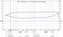
as somebody in this thread said that i should try the flattest one, i finally use the riaa filter which has the response/phase as seen in the picture. I have not listened it yed but i think that it should be ok.
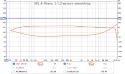
As a second option i always have the elektro magazine filter as seen in the second picture (red curve). It is not as flat as the previous one but i dont know which of theese two filters will sound better. I have a ortofon silver stylus and i dont know its response (for example if it sounds too bright i will choose the red curve response). If someone knows this stylus and how it performs please let me know.
As a second option i always have the elektro magazine filter as seen in the second picture (red curve). It is not as flat as the previous one but i dont know which of theese two filters will sound better. I have a ortofon silver stylus and i dont know its response (for example if it sounds too bright i will choose the red curve response). If someone knows this stylus and how it performs please let me know.
Attachments
Last edited:
- Status
- This old topic is closed. If you want to reopen this topic, contact a moderator using the "Report Post" button.
- Home
- Amplifiers
- Tubes / Valves
- riaa amplifier