Some original 6DJ8 data sheets had two different filament to cathode maximum voltage ratings.
That was because with the tube wired in series for Cascode mode, the top triode needed a higher maximum filament to cathode voltage rating.
You have to pay attention to which triode is wired for the top half of that cascode stage.
As a cascode RF amplifier:
Of course if you cap couple the plate of the common cathode triode stage, to the cathode of the grounded grid stage, it does not matter.
But then you need a separate load for the common cathode stages plate, and a separate inductor (current sink) from ground to the cathode of the grounded grid stage (usually a bias resistor was in series with the inductor).
The same attention to the separate filament to cathode voltage ratings of the two 6DJ8 triodes, needs to be accounted for in SRPP stages too.
couldn't the circuit linked in post #1 be improved by direct coupling the first stage to the second?
How is that better? Save a few parts?
The AC-coupled form does not slam the second grid to B+ at turn-on, like a DC-coupled form would.
Yes, thousands of DC-coupled amps lived millions of hours just fine. I'm indifferent. But not inclined to change a known-good(?) plan on a thin whim.
Slamming the grid of a tube that is RC coupled is a matter of timing and circuit particulars.
Direct Heated B+ rectifiers; Cathodic B+ rectifiers; Solid State rectifiers
DHT output tubes, DHT driver tubes, cathodic output tubes, cathodic driver tubes.
And the combinations thereof.
If B+ comes up before a tube is warm, the plate will be at B+.
The Cap of the RC coupling may cause the grid of the next tube to rise all the way to B+ (only temporarily, until the cap charges).
If you look at some of the amps on this forum, you will see 4uF coupling caps and 1 Meg Ohm grid resistors. That takes a long time for the cap to charge.
Each circuit has a different combination; many of them that have RC coupling Do Cause Grid Current at power-up.
And then there is what happens during a Hot-Start (the amp is warm, then the power goes off and comes on again before the tubes cool down).
I know of instances of cooked grids on 12AX7 tubes in some Audio circuits.
That wire is extremely fine.
The 12AX7 grid is Not designed for RF Oscillator service.
Try a 6J6 instead. The maximum grid current is rated in the data sheet.
Oh . . . and did I forget to say that I love to use RC coupling between the driver(s) and the output tube(s).
Post #1 has an RC coupling of 0.1uF and 1 Meg Ohm. With B+ applied and Cold 6DJ8 cathodes, the cap will charge up 63.7% of the 250 B+ in one time constant (0.1 Second). That is OK.
A Hot- Start instance with a collapsing B+ and then B+ coming on again quickly is probably OK too.
. .. But a 1uF cap there might be kind of unfriendly to the grid.
Last edited:
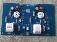
I have published a project of a line premap on Audioreview in Italy; it is simply but efficent
And I developped some pcb.
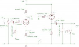
This circuit has some point where i possible to select fixed bias or autobias; in addition there is a matrix to change the filaments to use 6DJ8/6N6/6H30 or 12AU7/12BH7/ECC99; there is an option to insert also a tone control
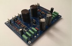
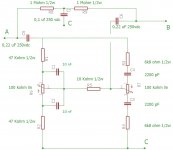
In addition there is the possibility to have an HT ss stabilized board; it has two channel compeltely separated and regulated.
And I developped some pcb.
This circuit has some point where i possible to select fixed bias or autobias; in addition there is a matrix to change the filaments to use 6DJ8/6N6/6H30 or 12AU7/12BH7/ECC99; there is an option to insert also a tone control
In addition there is the possibility to have an HT ss stabilized board; it has two channel compeltely separated and regulated.
Attachments
It is a Line preamp with the possibility to use different tubes changing the matrix for filaments and just two resistors ( in case).@waltube Could you please also share the schematic with values? Can this scheme used as tube preamp? What are the measurements for harmonic distortion %, typical THD at 1W, PSRR and input sensitivity and max output V rms?")
Alsom it is possible to use a fixed bias or autobias.
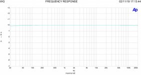
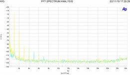
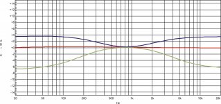
In attach the lab test
The freq. answer
The FFT
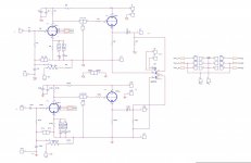
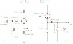
The schematic with 6N6 double triode and fixed bias
The Vout is 2 Vrms, The Thd is around -50/-55 dB depends on tube selection
Attachments
E88CC is the Special Quality (SQ) version of ECC88 which was meant to last 10,000 hours. Gold plated pins so bling bling too.No, a 6922 is an E88CC ; the American designation for ECC88 is 6DJ8 as the bloke makes clear in his article.
HiNice circuit. Thanks for sharing. What voltage is the P1/P1 supply for 6N6, and what is the bias voltage value you like?
The Vdc is around 200-220, the 6N6 is robust
The Ibias I prefer is within 8-10 mA; the Vbias can very.
The 6N6 need some selction; also ggod is 6H30 but more expensive
Thank you! Do you have idea how to get these THD numbers lower? If I like to use 6DJ8 tubes then what values I need to change in this scheme?
Hi
At 2 Vout the THD is quite low; with 6H30 will be better
I check for ECC88 leaving the same R value and it works fine; if you use fixed bias you can play with negative voltage fixing a good point.
In addition is possible to insert a tone control just connectin 3 points/channel; I made a little pcb
Attachments
https://diyaudioprojects.com/Tubes/ECC802S-ECC82-12AU7-Tube-SRPP-Preamp/
I built this one couple of years ago. Easy to built, point to point soldering. Great as a first project?
I built this one couple of years ago. Easy to built, point to point soldering. Great as a first project?
Hello everyone
So I've been looking into building a tube preamp and came across this website: DIY 6922 / E88CC Tube preamp
The schematics are there, but not fully complete. In other words, the PSU name/schematic is nowhere to be found, as well as the place to apply the 6/12v for the tube from the power supply. Any help is greatly appreciated.
Maybe a bit late , but if this is your first go at building a tube preamp , I would highly recommend you try it with low voltage
6gm8 ( ecc86 ) triodes first . These have a maximum plate voltage of 30 Vdc , so 25 Vdc voltage supply rails work very well with these triodes .
I say this because anything after 50 Vdc can be lethal .
John Broskie has been mentioned here - IMO the quality of his boards is top notch .
His Akido Cathode follower , or the dual supply cathode follower designs are very good .
However , know that these are buffers .
As a subjective comment , IMO the Akido cathode follower sounds a bit more refined ,
where as the cathode follower that uses a dual supply sounds more open .
With dual +/- 25 Vdc rails and a 6gm8 , I pushed the current up to 5.6 mA and it sounds great.
The cathode resistors were 68 R
You may want to tinker around with this load line calculator .
https://www.vtadiy.com/loadline-calculators/loadline-calculator/
.
The difficult part of the project may be finding these tubes , but its well worth the effort .
.
Nigel ,
Do they make red LED's that flash on and off ?
Caps charged up to high voltages scare the hell out of me .
You have quite a bit of experience with triodes .
Quick version of the Question : Do you think an ecc88 or e88cc will work OK with a plate voltage of 83 Vdc ?
Long version of the Question : John Broskie's Akido Cathode follower ACF-2 sounds great with 6gm8 ( ecc86 )
using 25 Vdc rails with the current pushed up to 5.6 mA .
https://glass-ware.stores.yahoo.net/acpcbandusgu.html
But I have a quite a number of 1960's vintage 6922 ( e88cc ) and 6dj8 ( ecc88's ) .
So I'm building a ACF-2 version for these triodes with a passive power supply . *
The problem is finding a transformer that gives the plate voltage of around 130 Vdc.
Looking at the load line calculator ,
https://www.vtadiy.com/loadline-calculators/loadline-calculator/
for an ecc88 a plate voltage of 130 Vdc , biased at 11.5 mA , looks like its right in the sweet spot .
According to this , I think the cathode resistor should be 130 R = 1.47 Vdc / 11.5mA.
Hammond makes 185D230 transformer , which could either give 83 Vdc or 165 Vdc rails .
https://www.hammfg.com/electronics/transformers/power/185
I can't find an E core transformer that would give dual +/- 130 Vdc rails with a passive supply .
The thing about this cathode follower is that the non linearities of the top triode , are canceled by the bottom triode .
The bottom triode does not act like a CCS - but rather its kind of like a non linear resistor
and Rk in the bottom triode sets the bias current .
* IMO the power supply is the key to great piece of audio equipment , so I'm using a separate dual rail supply .
.
NIgel ,
Right thanks for your advise on this , I'll give it a go .
Something I never noticed looking at datasheets ,
according to the load line calculator , turns out an ecc88 has a different family of curves than an e88cc .
Also, one trick I discovered .
Imagine spending a huge effort getting a plate power supply with a beautifully clean B+ and clean analog ground .
Not getting into a debate on whether to use AC or DC for the heaters,
I use one of those 3 pin regulator chips , and 2 RC filters , to supply DC to the heaters .
Recall , the heater supply should not be left floating wrt to the cathode .
But the second the DC heater ground , is connected to the beautifully clean analog ground noise is added .
This is regardless of whether the heater supply is " lifted " with a resistor voltage divider or not .
So I would recommend connecting something like 47K between the voltage divider that " lifts" the heaters
and the ground of a DC heater supply .
The voltage drop across the 47K is next to nothing .
.
IMO the 47K makes quite an improvement .
.
- Home
- Amplifiers
- Tubes / Valves
- 6922/E88CC Preamp