For now at least, I plan to stick with the original Mullard 5-20 design and only once I've got it working properly will I consider tweaking the design.
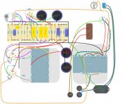
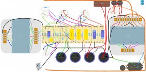
I've drawn up a diagram in DIYLC which hopefully is correct but errors may have slipped the net as I've had a few interruptions and have a cold on the way which never helps. Looks a bit like spaghetti but I'll try to wire it far neater than I can draw it on a pc.
Out of interest, are there any preferred tubes for EF86 and ECC83? I've seen so many different ECC83's that I'm a little baffled. I was thinking just the plain JJ ECC83S and either a JJ or electro-harmonix EF86. Also, is there any benefit to using the shielded noval socket?
Attachments
I've drawn up a diagram in DIYLC which hopefully is correct but errors may have slipped the net as I've had a few interruptions and have a cold on the way which never helps. Looks a bit like spaghetti but I'll try to wire it far neater than I can draw it on a pc.
Thanks to the pointer to DIYLC! I have been struggling with some very simple circuits I want to build on strip board, and that looks perfect!
First observation, R1 and R2 are not configured like that. R2 (4.7k) goes from input to pin 9. R1 (1M) goes from input to ground. Ground goes to input ground.
I would also redo the bus bar system to be more like 'star' ground. At least focus the HT centre tap to the negative of C15 and fan out from there...
And what is the grey thing top right, next to mains switch, with the heater pair going to it?
I would also redo the bus bar system to be more like 'star' ground. At least focus the HT centre tap to the negative of C15 and fan out from there...
And what is the grey thing top right, next to mains switch, with the heater pair going to it?
Good spot. I think I've also taken the feedback off the wrong secondary point on the OPT. The thing in the top right wired off the heater pair is supposed to be the "pilot light". I've tried to draw this following the original mullard design as best I can, which ironically, doesn't appear to use a star ground system.First observation, R1 and R2 are not configured like that. R2 (4.7k) goes from input to pin 9. R1 (1M) goes from input to ground. Ground goes to input ground.
I would also redo the bus bar system to be more like 'star' ground. At least focus the HT centre tap to the negative of C15 and fan out from there...
And what is the grey thing top right, next to mains switch, with the heater pair going to it?
Attachments
You have 3 external fuses on your drawing, but I took some advice from the fusing schema from Valve Wizard (Merlinb on this site) ...
Fusing
If you just use one fuse on the Primary, from the line wire, and use two in-line fuses on the secondary of the power transformer, then you have a better protection on the transformer, and save yourself two holes to be drilled in the bargain ;-)
Fusing
If you just use one fuse on the Primary, from the line wire, and use two in-line fuses on the secondary of the power transformer, then you have a better protection on the transformer, and save yourself two holes to be drilled in the bargain ;-)
Yes, the 6Π3C-E (6p3s-e) tubes are still affordable. And they are perhaps (in practice) more of an equivalent of the 6L6GC/7581 than 5881. But they are rapidly demanding higher prices (after being discovered). I have personally used and sometimes preferred those to EL34s in my EICO HF-87.
I've come to love the 6p3s-e too. I've gone through heaps of different valves in a pair of 5-20esque mono blocks and have settled on the 6p3s-e as the perfect compromise of performance and value. Although, I stocked up 5 years ago when they could still be had for the price of a beer (and beer could still be had for the price of a subway ticket). Supplies from the online Russian dealers seem to have gone..
...The thing in the top right wired off the heater pair is supposed to be the "pilot light". I've tried to draw this following the original mullard design as best I can, which ironically, doesn't appear to use a star ground system.
Yes, I should have realised... yes it will work fine as you/ Mullard have designed it, but the thing with the original design it was for a single mono amplifier. Then the safety standards of the time were not so stringent. Further the noise ratio was not so critical, you have to compare it to its contemporaries.
Again just my opinion, as you are building 2 mono-blocks for stereo, you should isolate the input sockets ground from the chassis. It is easy to get ground loop hum / noise with chassis based grounding using two amps the same.
The problem then is you loose the earth connection to the chassis. Not good.
The preferred way today to earth the chassis is to bolt the earth wire directly to the chassis close to the mains input - then take another connection from there to the bus bar / input socket connection. If you do get a ground loop then, you can 'ground lift' one of the wires, leaving both chassis earthed.
Its worth reading this by Valve Wizard http://www.valvewizard.co.uk/Grounding.pdf and have a look at Rod Elliott's site Elliott Sound Products - The Audio Pages (Main Index) .
Again in today's world, the HT ac centre tap goes to the first smoothing capacitor ground tag, then the second cap etc. to the bus. That keeps the charge pulses in the wire to a minimum. Likewise the two centre taps of the 6.3 volt windings should have individual wires to the point on the bus that the earth wire (above) goes to.
There are variations and other opinions, so best advice is build it as you see fit, but make sure you have plan 'Bs' and 'Cs' and leave the grounding options a little longer than you want. You can move them then / try other options to get the least noise. It is all part of the fun!
Alan
My no-instrument hum minimisation method
Alan is right, you want to leave yourself grounding options. My equipment-free method involves cheap headphones.
Once the hum is not bad through speakers leave them connected or replace them with ~8 ohm resistors.
Short the inputs to your amp. Using a cheap pair of low impedance 'phones or ear buds, these are quite sensitive to work on cell phones, tabs and the like. A cheap jack with some leads (paralleling left and right) is useful.
Connect the 'phones to the speaker jacks/posts THEN put them on or close too your ears. Judge the hum level.
Disconnect the phones, shut the amp off, try another grounding scheme, power up, reconnect the phones. Your short-term audio memory should be good enough to notice improvements or the opposite.
Cheers, Steve
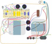
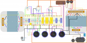
I've been redrawing some of the plans since yesterdays pointers. I've incorporated some of the grounding suggestions made above. I also rotated some of the sockets to better suit the wire entry points. Hopefully there are no errors on this one.
The R1 and R2 error persists.
You have left the bus bar floating. Take a wire from the earth point to the input connector ground tag.
Take the black wire from C15 straight to the 0 volt connection of the 410-0-410 tap. Give the two 0 volt 6.3 volt connections each their own wire either to the earth tag or to the bus bar where the black wire from C10 meets it.
Alan
Thanks for that. This should come in handy once I get that far as I have no doubt that grounding will be fiddly.Alan is right, you want to leave yourself grounding options. My equipment-free method involves cheap headphones.
Once the hum is not bad through speakers leave them connected or replace them with ~8 ohm resistors.
Short the inputs to your amp. Using a cheap pair of low impedance 'phones or ear buds, these are quite sensitive to work on cell phones, tabs and the like. A cheap jack with some leads (paralleling left and right) is useful.
Connect the 'phones to the speaker jacks/posts THEN put them on or close too your ears. Judge the hum level.
Disconnect the phones, shut the amp off, try another grounding scheme, power up, reconnect the phones. Your short-term audio memory should be good enough to notice improvements or the opposite.
Cheers, Steve
I’ve only just figured out my R1/R2 error. This cold has definitely taken its toll on me. I’ve completely redone the layout, basing it on the same fundamental design as the 5-10. A long, slim chassis with the transformers at opposite ends. IMO, it has allowed for simpler wiring routes. I’ve tried to implement your grounding in this new plan. I’ll post the new drawings up when I’m back on the pc and I’ve fixed that R1/R2 issue.The R1 and R2 error persists.
You have left the bus bar floating. Take a wire from the earth point to the input connector ground tag.
Take the black wire from C15 straight to the 0 volt connection of the 410-0-410 tap. Give the two 0 volt 6.3 volt connections each their own wire either to the earth tag or to the bus bar where the black wire from C10 meets it.
Alan
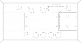
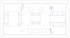
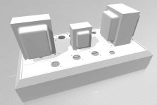
New drawing and the top plate design. I'm undecided whether to use the choke underneath as drawn or whether a shrouded version with feet like the other two transformers, situated in between the two transformers. The latter might be neater but the choke would be more expensive and sit directly above the turret board.
I've left the heater wiring and the mains wiring unfinished as working with wires in DIYLC once things get complex is tedious as it gets very slow. The wiring will run into the corners and directly to the valves. The wiring from the valves will run straight and parallel where possible, I just can't draw it like that in the software. I may try a hand drawn approach if the layout is considered sensible.
I've left the heater wiring and the mains wiring unfinished as working with wires in DIYLC once things get complex is tedious as it gets very slow. The wiring will run into the corners and directly to the valves. The wiring from the valves will run straight and parallel where possible, I just can't draw it like that in the software. I may try a hand drawn approach if the layout is considered sensible.
Attachments
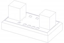
I've made my decision on the choke and gone with the stand mounted version that fits the specs perfectly. (10H 200mΩ 180mA) This will be mounted centrally between the HT and output transformers. The chassis is currently 400x200mm metal sheet with an 18mm thick wooden frame/base.
I've also redrawn the diagram using simple straight wiring to try and make it easier to read vs all the curly wires of the other diagrams I've done so far. It's still rather overwhelming but it's a bit easier to follow. The software is also much faster dealing with non curved wires which helps.
I've also redrawn the diagram using simple straight wiring to try and make it easier to read vs all the curly wires of the other diagrams I've done so far. It's still rather overwhelming but it's a bit easier to follow. The software is also much faster dealing with non curved wires which helps.
Attachments
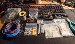
Further digging through my parts bin today found some more useful components for this project.
2 Neutrik phono sockets
4 more Octal sockets (also found 7 matching transformers with them)
Some TDC11 & TDC10 250mA 6.3x32mm fuses (depending on whether I need F or T type for the HT fuses)
Some 20mm 2A fuses in both T and F types.
Some 330pF 160V polystyrene capacitors for the feedback loop to use instead of the ceramics. I also found some 47pF parts but I believe 160V may not be sufficient
Some barrier strips
8 Rubber feet
A reel of 18 gauge tinned copper wire (pretty sure I have a reel of 16 gauge hidden elsewhere)
A selection of hookup wire
A selection of sleeving
Attachments
Just looking in more detail at what valves to get for this now. Is there any advantage to paying a little more for the following over going with JJ parts for everything:
EF86 - Tung-Sol EF806 (£25), Mullard NOS (£28) or GE 6267 NOS (£25)
ECC83 - Tung-sol 12AX7A (£19.75), Westinghouse 6189 (£21), GE JAN 5751 (£28.50)
EL34 - Tung-sol EL34B
GZ34 - Sovtek (£17.50) Watford valves claim this is superior to the JJ part.
I'm not too sure on the suitability of the ECC83 alternatives as too many shops claim a lot with respect to what fits in place of other items. The ECC83 has so many options that I'm a little baffled as to the ideal choice. JJ offer a vast number of variations too. My primary concern is reliability and lifespan, which I know will be hard to predict. Sound quality is obviously something I want to be good but is more subjective. Having had zero previous experience with valves, I'm having a hard time finding info due to the sheer quantity of reviews that cover guitar use not hi-fi use.
In other news, this is the current BOM. Eye watering when totalled but the sowter output transformers that I decided to buy have added over £400.
Mullard 5-20 BOM
For EF86s, you're way, way, way better off with those NOS tubes. I wouldn't pay the extra 3 quid for the Mullard print, just go with the GE.
A 6189 is a 12AU7, so that shouldn't be on your list for a strict 5-20. I'd get something old stock if the cost difference isn't substantial.
A 6189 is a 12AU7, so that shouldn't be on your list for a strict 5-20. I'd get something old stock if the cost difference isn't substantial.
Kel for EF86 you can also buy and try 6J32P for example.
6J32P = EF86 = 6267 tube. Pentode ― Hi-End vacuum tubes, sockets, capacitors, nixie. Retail and wholesale to worldwide.
I have bought from this seller 2-3 years back some tubes.
There are other too.
Compare the EL34 to 7591 from JJ or EH they should also work with new bias
setting.
I only have build some SE amps, enough for my listening level.
Kel for EF86 you can also buy and try 6J32P for example.
6J32P = EF86 = 6267 tube. Pentode ― Hi-End vacuum tubes, sockets, capacitors, nixie. Retail and wholesale to worldwide.
I have bought from this seller 2-3 years back some tubes.
There are other too.
Compare the EL34 to 7591 from JJ or EH they should also work with new bias
setting.
I only have build some SE amps, enough for my listening level.
Aren't those 6J32P's supposed to be quite strongly microphonic? Otherwise, if they are good performers, that's a very good price.Bangala is correct. I didn't adequately qualify my statements regarding EF86s, which is that a lot of the new production tubes will not quite hit their DC operating points correctly. The 6J32P, however, is a flawless performer in that regard.
What about the ECC83/12AX7? Is a 5751 worth considering?
- Status
- This old topic is closed. If you want to reopen this topic, contact a moderator using the "Report Post" button.
- Home
- Amplifiers
- Tubes / Valves
- Planning first valve amp build