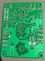
Got problems with this rectifier and regulator unit. It puts out some 100hz ripple that causes hum in the preamp. It uses an EZ80 as rectifier, 6C19P as power element, EF80 as error amplifier and a 12AU7 as reference. If I remove the 12AU7 reference tube the 100hz ripple is gone and no hum. Of course, the voltage drops to about 200Vdc. I know, some of you will find this circuit a bit strange but this is what the manufacturer has done. But clearly, something is wrong.
Attachments
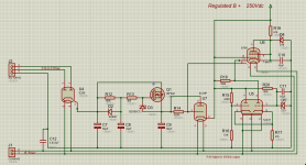
I am trying to make sense of the circuit as drawn, but it is drawn is such a way that makes this very hard to comprehend. I will study if further and try to come up with an answer for your problem.
Anyway you can make a very good supply with 6C19 and EF184/EF80 by CCS loading the pentode with a DN2540 at about 5mA current.
Alternatively, i can send you gerbers for a 6C19 EF184 85A2 supply, that is rather conventional in set-up, its power supply rejection isnt great, but its simple available.
Edit, ive taken a look, and there can be a problem with heater to cathode isolation that allows hum to appear at the cathode, of the long tailed pair voltage comparator, alternatively the wiring could allow for hum pickup.
I think the design is quite Meh, because there is no frequency compensation, and the heaters are all on the same winding.
Attachments
Last edited:
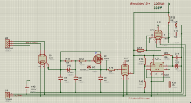

Yes, this is reasonable.This is more like it. But with the resistors (440k-51k) and zener (33V) the output is more or less ~330V.
Mona
But i have no clues of why it's not working, i would have measured a lot of stuff
before i could say whats wrong.
The obvious is to try with another ecc82 / ef80 first. Check the 75V zener then.
Yes, this is reasonable.
But i have no clues of why it's not working, i would have measured a lot of stuff
before i could say whats wrong.
The obvious is to try with another ecc82 / ef80 first. Check the 75V zener then.
Every tube and capacitor have been replaced with new ones. The other componets have been checked and is working as they should. The preamp is a well knowned german brand but the manufacturer refuse any help. Why, I dont know.
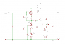
Very complicated schema. This is my version, which I use for phono tube preamp. Maybe it helps.
Thats a very good schematic, Alternatively you could remove the decoupling on the EF80's G2 and run a high value resistor from the raw B+ to G2 of the EF80. In that way you could reduce output ripple.
Have you seen my comment about CCS loading the EF80? this is something to consider, cause you can get up to an order of magnitude higher amplification from the EF80 that way. The EF184 is pin compatible by the way and has slightly higher Mu then EF80.
PS if all else fails, i could help you cook up a new PCB for the Phono amp, that uses a simpler yet effective regulator.
It says 250Vdc on the pcb but it's actually 230Vdc out on top of R19.This is more like it. But with the resistors (440k-51k) and zener (33V) the output is more or less ~330V.
Mona
Thats a very good schematic, Alternatively you could remove the decoupling on the EF80's G2 and run a high value resistor from the raw B+ to G2 of the EF80. In that way you could reduce output ripple.
Ok, I`ll give it a try. Thanks.
What brand ? It's no use hiding the brand , in fact it's contraproductive especiallyEvery tube and capacitor have been replaced with new ones. The other componets have been checked and is working as they should. The preamp is a well knowned german brand but the manufacturer refuse any help. Why, I dont know.
if their support is less then perfect.
Another question, did it work before replacing components ?
If so, the values of R15,R16 and/or D5 are different from those in the schematic.It says 250Vdc on the pcb but it's actually 230Vdc out on top of R19.
Mona
If so, the values of R15,R16 and/or D5 are different from those in the schematic.
Mona
Please, believe me. I`ve gone over the pcb so many times now that I`m 100% certain the schematic is correct.
 At least until someone prove me wrong.
What brand ? It's no use hiding the brand , in fact it's contraproductive especially
if their support is less then perfect.
Another question, did it work before replacing components ?
Wall Audio Opus 100 Sym. Its been like this from day one. Bouht it cheap as I thought I could fix it, but no, not any luck so far.
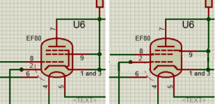
Well, here it isPlease, believe me. I`ve gone over the pcb so many times now that I`m 100% certain the schematic is correct.
Left is your version.
But, why that EF80, can be done without it.
Mona
Attachments

Last edited:
This thread makes me want to learn about regulators... Say I have 350VDC and I want 300VDC regulated and I have a 6N2P for the error voltage, a VR tube for the reference, and a 6080 for the pass device. How would that look schematic wise?
Or say I want a regulated 300VDC power supply for up to 1A of current. What then? Several 6080's in parallel would work but would be such a waste IMHO. A MOSFET would be better in this case? Could I use an NE-2 at the VR reference?
Explain it like I'm 5 years old if you care to.
Or say I want a regulated 300VDC power supply for up to 1A of current. What then? Several 6080's in parallel would work but would be such a waste IMHO. A MOSFET would be better in this case? Could I use an NE-2 at the VR reference?
Explain it like I'm 5 years old if you care to.
Last edited:
350 in and 300 out doesn't leave enough headroom for -10% mains voltage fluctuation. 400 in 300 out would be recommended.
6N2P error amplifier is a possibility but normally there is a dual triode and a pentode VAS to increase loop gain, a simple 6N2P resistor loaded wont go over a gain of ~80
Look at the schematic of the tektronix 545A for example of how a 6080 pass device is controlled.
As per my suggestion in the thread, i suggest you look at a EF184 error amplifier that is CCS loaded, ive built that and have gotten under 0.1mV measured noise that way.
Edit, for lower dropout voltages a mosfet is a possibility, however given the voltages involved if you want any kind of current limit you are wise to buy real "Linear" mosfets. The current switching optimized mosfets go unstable and self destruct in DC regulator duty.
Last edited:
Thanks for the tip!
The only "regulator" I've built was a simple shunt regulator using VR tubes or zeners. So far, my voltage "regulation" comes from oversized components. For instance, if I use a 100VA transformer, I might get a swing of 30V on the B+ of an amp playing silence vs full blast, but if I use a 500VA coil, that drops to a couple of volts.
My monoblocs use a power supply that is 360V open circuit, 320V silence (400mA), 305V (1400mA) full blast. I was wondering if there was a way to use some regulation scheme to make it 300V from this all the time, but I doubt that's possible EDIT: without SMPS.
- Status
- This old topic is closed. If you want to reopen this topic, contact a moderator using the "Report Post" button.
- Home
- Amplifiers
- Tubes / Valves
- Problem with tube regulator