What's U7 for?
U7 is the pass tube, it handles most of the work load.
This thread makes me want to learn about regulators... Say I have 350VDC and I want 300VDC regulated and I have a 6N2P for the error voltage, a VR tube for the reference, and a 6080 for the pass device. How would that look schematic wise?
Or say I want a regulated 300VDC power supply for up to 1A of current. What then? Several 6080's in parallel would work but would be such a waste IMHO. A MOSFET would be better in this case? Could I use an NE-2 at the VR reference?
Explain it like I'm 5 years old if you care to.
I don’t think you will have enough voltage swing to drive the 6080 grid without configuring it in a cascode, the cathode coupled design wouldn’t have enough gain.
Attachments
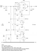
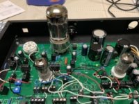
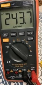
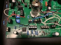
I took your basic setup and did some prototyping, except I’m using a 6080 pass a EF86 For control tube and a 12AT7 for the error amp. Works nicely so far, very similar to my spice simulation. My voltage reference and voltage divider are a little different.
Attachments
- Status
- This old topic is closed. If you want to reopen this topic, contact a moderator using the "Report Post" button.