I’m modifying a 4-way 12AX7-based crossover and measuring unexpected attenuation in the low pass stages.
LTSpice simulations show no attenuation.
For example, this is the 125Hz low pass stage.
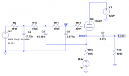
The 35Hz low pass stage is similar.
Component values are from TCJ Filter Designer.
For reference here is the 35Hz high-pass stage:
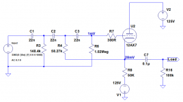
The high pass stages (there’s a 35Hz high pass and a 125Hz high pass) show approximately 0.3dB or so attenuation in the pass band as you’d expect.
The 35Hz low pass and 125Hz low pass filters show 9dB and 7dB of attenuation respectively.
Here’s the 125Hz low pass amplitude vs frequency superimposed on the 35Hz high pass amplitude vs frequency:
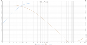
Pete Millett mentioned problems matching 12AX7 low pass and high pass stage gains due to the high output impedance of the 12AX7 cathode follower but not to this extent.
Can anyone suggest what the problem might be here please?
Next step is to try a CCS in place of the cathode resistors to take ra out of the equation.
Before anyone suggests switching to a 12AT7 or 12AU7 I'm reluctant to do that because it would mean modifications to the power supply.
LTSpice simulations show no attenuation.
For example, this is the 125Hz low pass stage.

The 35Hz low pass stage is similar.
Component values are from TCJ Filter Designer.
For reference here is the 35Hz high-pass stage:

The high pass stages (there’s a 35Hz high pass and a 125Hz high pass) show approximately 0.3dB or so attenuation in the pass band as you’d expect.
The 35Hz low pass and 125Hz low pass filters show 9dB and 7dB of attenuation respectively.
Here’s the 125Hz low pass amplitude vs frequency superimposed on the 35Hz high pass amplitude vs frequency:

Pete Millett mentioned problems matching 12AX7 low pass and high pass stage gains due to the high output impedance of the 12AX7 cathode follower but not to this extent.
Can anyone suggest what the problem might be here please?
Next step is to try a CCS in place of the cathode resistors to take ra out of the equation.
Before anyone suggests switching to a 12AT7 or 12AU7 I'm reluctant to do that because it would mean modifications to the power supply.
Not the output capacitor
Thanks for the suggestion Mark. I've been doing all my measurements at the cathode followers to eliminate any contribution by the output capacitors or output transformers.
I bought a couple of 10uF capacitors for when I got to testing the balanced outputs so I tried replacing the 0.47uF with a 10uF.
The results were the same:
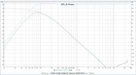
The 125Hz low pass is about 7dB lower at its peak than the 35dB high pass.
The -3dB points are way out so I'll need to adjust the filter component values. That will bring the output level peak up a bit.
Dave.
The ac-coupled output pole might be too close, try 10uF rather that 0.47uF
Thanks for the suggestion Mark. I've been doing all my measurements at the cathode followers to eliminate any contribution by the output capacitors or output transformers.
I bought a couple of 10uF capacitors for when I got to testing the balanced outputs so I tried replacing the 0.47uF with a 10uF.
The results were the same:

The 125Hz low pass is about 7dB lower at its peak than the 35dB high pass.
The -3dB points are way out so I'll need to adjust the filter component values. That will bring the output level peak up a bit.
Dave.
One problem with your lp stage is that in a real circuit the input may be AC coupled. There is currently no DC path from the grid to ground.
That's a result of posting the simulation schematic rather than the whole schematic. Here's the whole schematic:
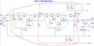
There's a balanced to unbalanced converter followed by a transformer volume control on the input. I've taken measurements at the output of the TVC and it's ruler-flat.
Hard to see anything wrong. If you have a scope just run through it. Try it without the OPT.
Yeah. I’m going to start by pulling the PCBs out and making sure I haven’t made any silly mistakes. I’m repurposing some commercial crossover boards so could be easy to do.
Must be en error - you could wire the grid of the final valve to the cathode of the first and bypass the filter. Only other thing is could be oscillating could could use a bigger gird resistor - unlikely, more likely a wiring error. Think I would expect cathode of first vale at -.5v and second about -1v. Check D2 is correct way round.
Last edited:
Your circuit is trying to pull about 2.5mA through a 12AX7 with 125VDC anode voltage. The grid is conducting and loading whatever is trying to drive it.
ps: Also, DC current drawn from the power supply is independent of the valve type, in this circuit.
All good fortune,
Chris
ps: Also, DC current drawn from the power supply is independent of the valve type, in this circuit.
All good fortune,
Chris
Last edited:
Your circuit is trying to pull about 2.5mA through a 12AX7 with 125VDC anode voltage. The grid is conducting and loading whatever is trying to drive it.
ps: Also, DC current drawn from the power supply is independent of the valve type, in this circuit.
All good fortune,
Chris
Thanks Chris. The first bit puzzles me because there's a -125V supply as well. So, total anode voltage of 250V.
The second bit is good to know. I want to try some of the other tubes that have been recommended.
Dave.
Chris is correct in that there is not sufficient voltage on the anode to get the current you wish. Since for 2.5ma the grid-cathode voltage is .5v and the grid is at 0v the cathode is at .5v that gives you only 124.5v between cathode and anode. That's not big enough for the 2.5ma. You need to either increase the plate voltage or use a different device. Try 12at7
Last edited:
Chris is correct in that there is not sufficient voltage on the anode to get the current you wish. Since for 2.5ma the grid-cathode voltage is .5v and the grid is at 0v the cathode is at .5v that gives you only 124.5v between cathode and anode. That's not big enough for the 2.5ma. You need to either increase the plate voltage or use a different device. Try 12at7
Thanks very much for the explanation. I understand now.
Fortunately I can easily increase the plate voltage.
The simulation worked fine with ±125V too.
I'll try the 12AT7 as well.
12AX7 models
I have previously compared Ayumi, Koren and modified Koren models. All produced essentially the same amplitude vs frequency curves and now that I go back and look, <100mv Vgk.
The most recent model on the "Vacuum tube Spice models thread" is this Rydel one.
This again results in the same amplitude vs frequency curve and <100mV Vgk.
If I'm prepared to accept a lower anode current I can just increase the cathode resistor. Increasing it from 50k to 75k results in a Vgk of 472mV.
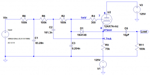
With the Rydel model again, the amplitude and phase vs frequency are essentially the same.
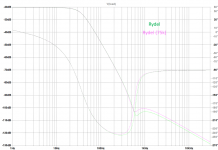
I've attached my model.
Your simulation showed on <100mV gid cathode which is not correct for the current. I suspect the model you have is not accurate under these conditions - try the ones on diyaudio.
I have previously compared Ayumi, Koren and modified Koren models. All produced essentially the same amplitude vs frequency curves and now that I go back and look, <100mv Vgk.
The most recent model on the "Vacuum tube Spice models thread" is this Rydel one.
This again results in the same amplitude vs frequency curve and <100mV Vgk.
If I'm prepared to accept a lower anode current I can just increase the cathode resistor. Increasing it from 50k to 75k results in a Vgk of 472mV.

With the Rydel model again, the amplitude and phase vs frequency are essentially the same.

I've attached my model.
Attachments
12AT7 biasing
Just looking at the average plate characteristics for the 12AT7 it doesn't look very linear in 2.5mA area.
Would it need something higher like 10mA?
Try 12at7
Just looking at the average plate characteristics for the 12AT7 it doesn't look very linear in 2.5mA area.
Would it need something higher like 10mA?
Up to you which way you go. You could simulate the 12at7 on ltspice and look and the harmonic distortion and compare with 12ax7. You could increase the plate voltage. Making the load resistor bigger will reduce your ability to drive the opt. At low frequencies the inductance and distortion of the transformer may be the limiting factor in which case a bit more current may be a good thing.
Up to you which way you go. You could simulate the 12at7 on ltspice and look and the harmonic distortion and compare with 12ax7. You could increase the plate voltage. Making the load resistor bigger will reduce your ability to drive the opt. At low frequencies the inductance and distortion of the transformer may be the limiting factor in which case a bit more current may be a good thing.
Thanks for the advice.
I don't want to reduce the current anyway in case I want to replace the cathode resistors with CCSs.
I measured one of the grid to cathode voltages and sure enough it was only 20mV. The filters work like that but the passband level is attenuated and it may be why the 3dB points aren't where they're supposed to be.
I'll raise the anode voltage temporarily by removing the "R" from the "LCRC" filter. If that fixes the problem there are a couple of options for permanently increasing the plate voltage.
...2AT7 it doesn't look very linear in 2.5mA area. ...
You are using it as a Cathode Follower, right? How nonlinear can it be with 50:1 of NFB?
The Gm at 100V 2.5mA is like 3,000uMho so the cathode impedance is OTOO 300 Ohms. The load impedance is OTOO 30k. So any nonlinear variation of Gm with current is reduced about 100:1.
With 250V total supply a plate-loaded tube will do about 50V peak at 5% THD. With 100% NFB a high-Mu triode will be like 5%/50 or 0.1% at nearly 50V peak. This will decline roughly as signal level so nearer 0.01% at 5V peak.
If you need less than 0.01% THD then you want several transistors.
Last edited:
- Status
- This old topic is closed. If you want to reopen this topic, contact a moderator using the "Report Post" button.
- Home
- Amplifiers
- Tubes / Valves
- Unexpected 12AX7 crossover filter attenuation