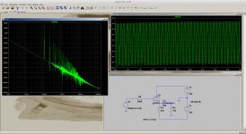
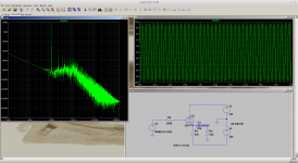
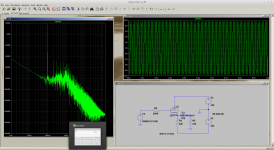
The LT spice simulation shows you are taking grid current with the 12AX7 and the output level is reduced. There is also considerable distortion. The 12AT7 works correctly and would allow you to increase the current to 4ma.
Thanks for that. I hadn't done any simulated distortion measurements but I was certainly measuring a lot.
Just to confirm that resolving the bias problem fixes the attenuation problem I increased the cathode resistor to 100k.
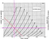
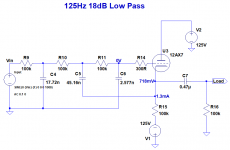
I measured Vgk to be 0.6V and Ia to be 1.3mA. LTSpice and actual measurements agree even if slightly different from the loadline estimates.
I'll order some 12AT7s. Increasing current isn't a problem because I'm currently using bleed resistors across the power supply capacitors to raise the current through the 10H inductors.
Thanks very much for the help.
Good. I think the 12AX7 is a bit weedy for what you want its really for small signal. The 12AT7 will work much better for you. As its a follower it will have reasonable rejection of the power supply - you may find just resistors rather than 10H will do in the supply.
Last edited:
I think the 12AX7 is a bit weedy for what you want its really for small signal. The 12AT7 will work much better for you.
Yes. I've been advised that "...the 12AX7 is pitifully inadequate. The 12AT7 delivers much better results and it sidesteps the slew-limited sound from 12AX7-based active crossovers".
Incidentally, when I first made the mistake of agreeing to modify this crossover, there was a single rail of 225V. A typical low pass filter looked like this:
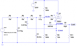
The 200k bias resistors were causing significant attenuation.
I'm investigating split rails to eliminate DC blocking capacitors, avoid the need for high voltage capacitors in the filters, avoid having bias resistors that are also part of the low pass filters, avoid having to have HT on the filter modules and allow CCSs.
Nice to uncover what you are actually doing!
Yes very good idea to move to split rail - I now see why the voltage got halved.
The CCS you could try in LT spice just to see if if reduces distortion. A don't know what drive level you are using but if you are only looking for 1v ppk I would not think it will make much difference. I think a resistor will be good enough.
Last edited:
Yes good idea to move to split rail. The CCS you could try in LT spice just to see if if reduces distortion. A don't know what drive level you are using but if you are only looking for 1v ppk I would not think it will make much difference. Since you are only looking at the bass frequenciesI think even 1% THD will have little effect, as other things (transformers, speakers) will dominate.
Thanks. 1V pp it is. It's a 4-way crossover: 35Hz, 125Hz, and 14kHz. There's a full range driver in there from 125Hz to 14kHz.
I will do both simulated and real distortion measurements with the CCS. I confess that was more for my own interest.
If you have access to the 6N1P at affordable prices they will also work well here as the 12AT7 would, and may be a bit more affordable overall, since they've not yet become a mainstream "gimme gimme" type of tube for audio. Same pinout other than heater wiring
Thanks. the Tubecad Journal Filter Designer I've been using uses those.
Unfortunately, the commercial PCBs I've repurposed would need a lot of mods to accommodate them. They were designed for 12AX7s.
- Status
- This old topic is closed. If you want to reopen this topic, contact a moderator using the "Report Post" button.
- Home
- Amplifiers
- Tubes / Valves
- Unexpected 12AX7 crossover filter attenuation
