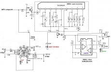
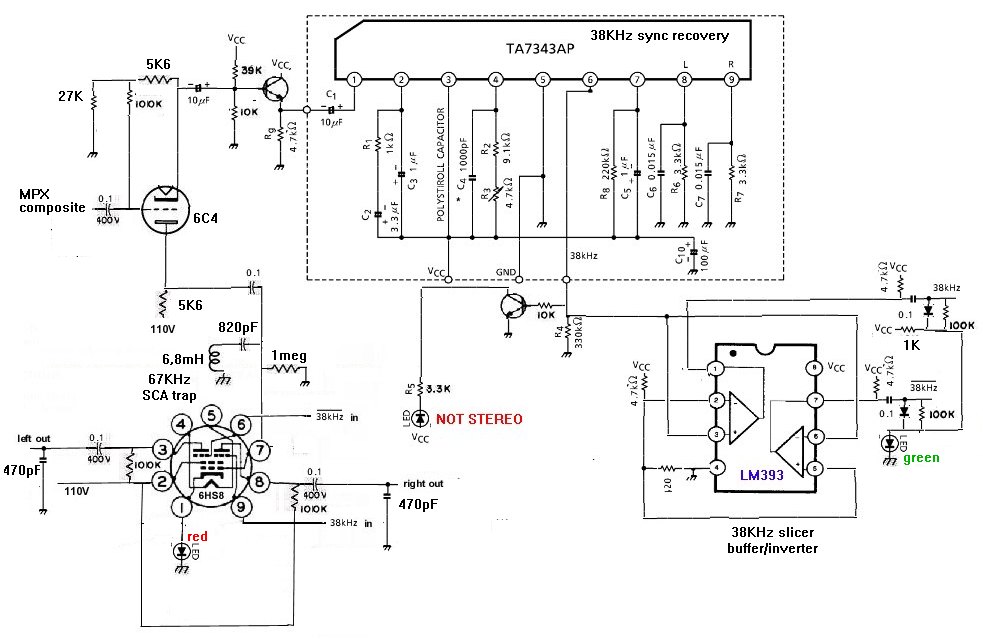
This is a FM MPX stereo decoder that uses a stereo chip to acquire the 38KHz switching waveform, and applies that to a "TV" tube that switches on and off the composite audio (which carries both the mono and the L-R difference signals) to produce left and right audio outputs. Idea is to use the chip to get a synchronized switching waveform. And the tube handles the audio signal that will go to your audio amplifier.

First thing is to find a chip that produces a 38KHz switching waveform. Turns out most of these stereo decoder chips don't provide that, keeping this signal inside itself. Some will provide 19KHz, but that's not useful. With my selected chip datasheet TA7343 I can get the 38KHz signal, but only if I don't have it directly drive an indicator LED. Doing that disables the chip's stereo demod section, but I'm not using that here. I found that when this chip loses lock on the stereo pilot signal, this 38KHz output pin goes much higher in voltage, thus I used a buffer circuit to light a "not stereo" LED indicator when that happens. The FM radio station essentially MUXes the left and the right channels by alternating the left and right audio signals at 38KHz rate. Making a sequence of L, R, L, R, etc at this 38KHz rate (time division multiplex) And my circuit recreates this 38KHz switching signal and essentially deMUXes the left from the right. The 6HS8 is a tube meant for color TV work, where this tube splits apart chroma information (which is also a MUXed signal of R-Y and B-Y chroma signals). In my circuit, each grid 3 has a square wave at the 38KHz rate that allows (when near +2V) its audio channel to get to its respective plate, or when this grid goes about -5V negative, cuts off the audio (disabling the audio that belongs to the other channel from reaching this plate). I used an LED to create a fixed bias for this tube, so these levels would always work). The LM393 dual comparitor chip produces 2 38KHz square waves, one inverted (it's essentially a data slicer). These square waves feed the grid 3's after passign thru a "DC restore" circuit that sets the voltage range of these square waves to levels the tube wants (also if stereo lock is lost, this circuit will clamp both signals to an "on" level, thus passing audio to both outputs). Otherwise, the comparitor chip will make a positive level on one output and a negative level on the other, thus cutting off one of the outputs.
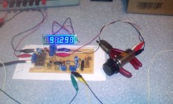
I appear to be getting good channel separation, but no, I haven't figured out which channel is the left, and which is the right, just yet!
First thing is to find a chip that produces a 38KHz switching waveform. Turns out most of these stereo decoder chips don't provide that, keeping this signal inside itself. Some will provide 19KHz, but that's not useful. With my selected chip datasheet TA7343 I can get the 38KHz signal, but only if I don't have it directly drive an indicator LED. Doing that disables the chip's stereo demod section, but I'm not using that here. I found that when this chip loses lock on the stereo pilot signal, this 38KHz output pin goes much higher in voltage, thus I used a buffer circuit to light a "not stereo" LED indicator when that happens. The FM radio station essentially MUXes the left and the right channels by alternating the left and right audio signals at 38KHz rate. Making a sequence of L, R, L, R, etc at this 38KHz rate (time division multiplex) And my circuit recreates this 38KHz switching signal and essentially deMUXes the left from the right. The 6HS8 is a tube meant for color TV work, where this tube splits apart chroma information (which is also a MUXed signal of R-Y and B-Y chroma signals). In my circuit, each grid 3 has a square wave at the 38KHz rate that allows (when near +2V) its audio channel to get to its respective plate, or when this grid goes about -5V negative, cuts off the audio (disabling the audio that belongs to the other channel from reaching this plate). I used an LED to create a fixed bias for this tube, so these levels would always work). The LM393 dual comparitor chip produces 2 38KHz square waves, one inverted (it's essentially a data slicer). These square waves feed the grid 3's after passign thru a "DC restore" circuit that sets the voltage range of these square waves to levels the tube wants (also if stereo lock is lost, this circuit will clamp both signals to an "on" level, thus passing audio to both outputs). Otherwise, the comparitor chip will make a positive level on one output and a negative level on the other, thus cutting off one of the outputs.
I appear to be getting good channel separation, but no, I haven't figured out which channel is the left, and which is the right, just yet!
Attachments
Last edited:
Get one of those little FM transmitters and play something through it on only one channel. https://www.amazon.com/Transmitter-...ansmitter&qid=1579232856&sprefix=fm+tr&sr=8-7
On mobile so link might not format right. But amazon has them for about 12 bucks
On mobile so link might not format right. But amazon has them for about 12 bucks
This is a FM MPX stereo decoder that uses a stereo chip to acquire the 38K ... Some will provide 19KHz, but that's not useful. ...
Pretty neat and timely idea in light of the thread a page or so back, contemplating building an all tube FM stereo tuner.
I built my simple tuner with LM/MC1310 as the decoder ( because I had them ) and, IIRC, it has one pin that brings out the 19 Khz square wave as a test point, so the VCO can be adjusted to lock.
Why couldn't that 19 KHz be doubled, and then split into opposite phases to drive the 6HS8?
edit: I'm thinking something like 4069 could work at 38 Khz.
I have room left on my board to add that circuitry, and probably even a 6HS8 ( if I have one ), so it might be fun to play with when I get unmired from other stuff.
Attachments
Last edited:
I appear to be getting good channel separation, but no, I haven't figured out which channel is the left, and which is the right, just yet!
Violins are on the left, brass is on the right, woodwinds in the center.
There, I fixed it!
Pretty neat and timely idea in light of the thread a page or so back, contemplating building an all tube FM stereo tuner.
I built my simple tuner with LM/MC1310 as the decoder ( because I had them ) and, IIRC, it has one pin that brings out the 19 Khz square wave as a test point, so the VCO can be adjusted to lock.
Why couldn't that 19 KHz be doubled, and then split into opposite phases to drive the 6HS8?
edit: I'm thinking something like 4069 could work at 38 Khz.
I have room left on my board to add that circuitry, and probably even a 6HS8 ( if I have one ), so it might be fun to play with when I get unmired from other stuff.
FWIW, I've been intrigued for some time by Mr. Turner's work. Perhaps Turner's 38 KHz. stuff could be combined with the OP's stuff as a way forward to a 100% tubed tuner. 6AL5s could substitute for SS diodes in the FM detector and frequency doubler circuitry.
I was thinking in terms of a 6JU8 in the ring demodulator, but the OP's 6SH8 setup is "sweet".
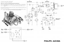
In the web page of Pacific TV there are several circuits for tube FM stereo demodulators. I was interested in make my own some years ago. Actually I postponed it to some years more. (Note I have no commercial linkage with them, but this page has several circuits for the repairman and I visited them several times.).
Did more work on it, seems I was getting interference from SCA subcarriers at 67KHz. Sounds like a swishing noise. I reconfigured the 6C4 buffer to give me a lower impedance signal that I then attached a 67KHz trap to. I think it reduced this problem (I have to listen to quiet passages).
Attachments
Did more work on it, seems I was getting interference from SCA subcarriers at 67KHz.
Would a signal carrying HD1 and HD2 present a similar problem?
You're most unlikely to encounter any SCA 67KHz in the real world of today. More likely HD if you are in the USA, or else harmonics of 19KHz.
Oh, about 15% of FM stations have SCAs.
HD doesn't show up on the FMed carrier, the HD signal is placed some distance from the main FM carrier something like 150KHz above and below.
One drawback of my scheme is that the resulting left and right channels have this big 38KHz waveform in addition to the audio. I reduced it some by connecting a 470pF cap across the left to right channels (the 38KHz waveforms are inverted compared to each other, but this cap may reduce separation on treble). That made the cathode follower happier, but it's still present. Your audio amp may not like it.
Attachments
Commercial MPX units used to have both 19 KHZ and 38 KHz filter sections in them, not like a CD player filter as they nailed that one specific frequency. Later units had pilot cancelling circuits to do this.
You just need a couple series L-C circuits on each channel. One for each frequency. The SCA issue is more like a CD filter scaled up in frequency. Thankfully, the SCA level is lower, so less work for a filter.
Keep at it, you're doing great!
-Chris
You just need a couple series L-C circuits on each channel. One for each frequency. The SCA issue is more like a CD filter scaled up in frequency. Thankfully, the SCA level is lower, so less work for a filter.
Keep at it, you're doing great!
-Chris
Commercial MPX units used to have both 19 KHZ and 38 KHz filter sections in them, not like a CD player filter as they nailed that one specific frequency. Later units had pilot cancelling circuits to do this.
<snip>
-Chris
The PLL he is using to recover the 38kHz subcarrier in theory should take care of all of that. Adjusting the loop bandwidth requires just a simple filter, should be covered.
I'd also look at that transistor follower, I'd set the input bias to ~1/2Vcc for best headroom. It may be clipping depending on what VCC actually is.
Hi Kevin,
Nope, the 67 KHz carrier is still out there at the edge of the audio from the 38 KHz carrier. Converting the 38 KHz down brings noise near the audio above 19 KHz or so. That's one reason why they dropped the modulation for SCA down. So the noise shows up in the difference channel. Just flipping great!
Stereo FM still sounds great.
-Chris
Umm, I wasn't talking about 67kHz SCA at all, that needs to be addressed separately since the chip internal SCA filter (if present) is irrelevant.
Pays to read what I wrote.
And the PLL has narrow enough bandwidth it doesn't care about the SCA subcarrier, it's the demodulator that cares.
He has a 67kHz trap, it may or may not be adequate.
Pays to read what I wrote.
And the PLL has narrow enough bandwidth it doesn't care about the SCA subcarrier, it's the demodulator that cares.
He has a 67kHz trap, it may or may not be adequate.
- Home
- Source & Line
- Analogue Source
- Build a FM stereo decoder using chip and tube