My Dad actually worked for Brüel & Kjær for a while.
What does that make you? An idiot?
My Dad worked at Mullard for a while, as well as next to Harwell in cryogenics and nuclear particle physics.
Does that make me an expert in muons, quarks or how to design an EL34?

The sort of ad hominem above illustrates perfectly why people get allergic to your increasingly hoarse voiced "research", which don't really belong on this thread apart from a certain amount of rather bemused curious interest.
People who can't cope with (valid) criticism usually end up doing that.
What are you saying?
Basically do it on the cheap because there is clearly neither the funding nor the interest.
I had this stuff last week...'we will show you how to do it" everyone else is wrong...and so forth... FUN on steroids!
Last edited:
Good
Trust me, not going to not try now.
That other heater guy is having fits, but he is being ignored.
Cheers, Joe
You're arguing that PMA's personal amplifier is making more distortion (0.1%) than some valve amplifiers from the mid-1950's. If this seems likely to you, stay the present course.
All good fortune,
Chris
Thanks, but it does seem that somebody at least should ask the question? What is the worst that can happen? That I am wrong? Dying without trying is worse.
But I am probably not the first to suggest this. I think in a round-about way Esa Merelainen has being saying something similar. He certainly has described the mechanism I want to explore. If he chooses to turn up here, he will likely say that he thinks tubes are old hat and only if you like tube distortion. I have his book and I don't think I have mischaracterised him.
What if we use a tube amp and able to show that the distortion Pavel measured distortion would be less? It's an if, but how would we be able to explain it then? But this is but one of many measurements that has to be tried.
Cheers, Joe
And there is every chance mixed mode feedback could help but really only if the speaker is directly driven, no crossoverNobody is arguing that the driver (tweeter) does not produce distortion, only that the amplifier is making that distortion worse and Pavel's measurements point to them being odd order.
Last edited:
I think in a round-about way Esa Merelainen has being saying something similar....he will likely say that he thinks tubes are old hat and only if you like tube distortion.
Being as I happen to know Finland quite well:-
1/ I doubt he has time for your "input"!
He certainly can't reply to me in under 2 weeks and I live "next door".
2/ I doubt very much the "old hat" nonsense, quite apart from the so called "tube
distortion" nonsense. (or why do the world famous Pultec still get used in Studios, as well as the incredible Neumann U47?)

3/ The hearsay presented in your post shows about as much technical acumen as the average smartphone user in a London bus,which is why you have to resort to ad hominem.
Most of the arguments in ESA's book have been debunked, and shown specially at LF to be invalid as he readily admits.
It's sheer amateurism from A-Z.
Use industry standards, and you might get taken a little more seriously.
Bruel & Kjaer.
Measurements:- Hewlett Packard.
...
'nuff said?
I'm not sure if pulling rank by calling big names from a century ago brings any value.
45 years ago, I did my thesis on low noise design, and I buried B&J by offering a 4x improvement over their Measuring Amplifier 2606. A couple of years later, during an AES convention, Matti Otala publicly called B&K's sweeping 2-tone IM measurement "idiotic".
Sorry if I hurt anyone's feeling, the point I want to make is simple: big $$$ don't guarantee quality results, and home made instrumentations can be just as good if not better, if you know what you're doing.
Including microphones?big $$$ don't guarantee quality results, and home made instrumentations can be just as good if not better, if you know what you're doing.
I suppose you must have improved them too?
Not sure if I was recommending using B + K actual measurement equipment, (I actually suggested HP) or is our daily use of B & K or DPA really that dumb?
Funny thing here,- each time I show an exception to your "valves are old hat" rule, there's a deafening silence, then a blatent attempt to change the subject, then exaggerating something unrelated to being 100yrs old.. (a century - REALLY?)

Tautology / circular arguments picking at detail is all it has become here.
>so VALID isn't it.
I didn't, but John Curl did, basically by changing just the gate resistor value; do a search here in DIYA.Including microphones?
I suppose you must have improved them too?
Don't get me wrong, I'm a 100% tube guy, both for Hifi and for guitar amps; I've tried for a few decades, and failed to find any solid state devices that sound as good. But then I have to speak up when someone says: "Hey, B&K and HP do it...", and my answer is: "So what"Funny thing here,- each time I show an exception to your "valves are old hat" rule, there's a deafening silence, then a blatent attempt to change the subject, then exaggerating something unrelated to being 100yrs old.. (a century - REALLY?)
We're in total agreement.Tautology / circular arguments picking at detail is all it has become here.
>so VALID isn't it.
And there is every chance mixed mode feedback could help but really only if the speaker is directly driven, no crossover
For the time being, get the evidence for a single driver, I don't intend to foresee too much. Once established, take it to the next level. I have already done some work on this, but with 1st order only. My Elsinore Project is a case in point.
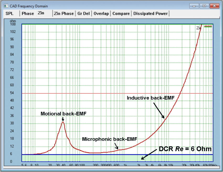
I could elaborate on something that got me in a heap of trouble when I used the term "back-EMF impedance" which is the excess impedance above the value of the DC resistance of the voice coil. Only the current that flows through the DC resistance part of the impedance dissipates heat.
Let us say the impedance at 3KHz is 17 Ohm, but the DC resistance is 6 Ohm.
We use a voltage source set to 6V and compare that with a current source producing 1 Amp.
Now if there was no back-EMF impedance, then both would result in 6 Watt because they are equivalents. But the back-EMF impedance means they are not and it is the relative change in dB that is important.
So this is the jig:
And here is the result. We will concentrate on the 3KHz, but note that you can pick any frequency and you can both calculate and measure the change in dB.
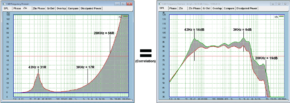
3KHz:
Zload Impedance = 17 Ohm
Re = 6 Ohm (Part A of impedance)
Back-EMF = 11 Ohm
Current drawn from voltage source, 6V/17R = 353mA
17R/Re = 2.83
Log(2.83)x20 = 9dB
Now check graph for dB-SPL difference = 9dB
-----
Vre = 0.353A*6R = 2.1V
Power Dissipation = 0.353A*2.1V = 0.75 Watt
Relative to 6 Watt (full 1 Amp) = 6W/0.75W = 8:1
Log(8.1)x10 = 9dB
-----
Not sure if you can see the pattern, but the Vre represents in voltage terms exactly what the driver is producing because it is only a function of current. Also note, you can do this calculation at any frequency and the maths and check the voltage to current variation in dB.
If you understand it, and I know that it might not be easy, yet the above proves that the dB-SPL output of the driver is directly related to the current and only current.
The key here is to understand that the excess impedance is back-EMF, where F stands for force and what does that mean? That this is a voltage source working against the current of the amplifier. It impedes the current, and hence I call it "back-EMF impedance."
Any driver imperfection will show up as a variation of the back-EMF impedance in series with Re, and hence modulate the current of the amplifier. The resulting Vre will show up the distortion. If using a current resistor like Pavel did, the voltage representing the current of the ampplifier is actually Vre being measured.
Ergo, if you have a bad resonance somewhere in the driver, that will show up in the current of the amplifier. But it might also trigger rubbish, like IMD, from the amplifier and each design could be different.
This also explains Pavel's measurement and why distortion was lower under current drive, because the modulation or corruption of the current cannot take place wihen the amplifier is putting out a fixed current. It resulted in a massive difference of 20dB of distortion. Had he used a tube amp, would it have been less?
So the tweeter's distortion was its own under current drive, but got worse under voltage drive, this now makes sense. We haven't reduced the distortion of the tweeter under current drive, it is just that it is worse under voltage drive.
Whew! There is of course more to it... I have just tried quickly to give you the idea.
Now watch that some will just dismiss all of the above and they will put some personal spin on it, like I don't know which end of a soldering iron to hold (no, I kid you not, that actually happened.
How is this on topic?
Because I believe that tube amplifiers have an advantage due to the output transformer providing a better current delivery system. I suspect that the many, particularly IMD products, will be reduced under those circumstances relative to SS with a feedback taken from the output. If so, it will put SS designs under scrutiny?
I'm off to bed. Now there will be chaos overnight I am sure and I will wake up to a storm.
C'est la vie.
Such is life.
Cheers, Joe
Last edited:
who in his right mind will claim that we can only hear one, the current sine wave and not the voltage sine wave?
Well i thot about it and what i think we have is the voltage amp applying a voltage to the speaker, but the speaker needs current to move. The voltage sin is converted to current using the reactive IV of the speaker (causing the 30• phase-shift. But it is the current that is moving the cone, so that is what we are hearing.
This should disappear, i think, if the same measures are done where the speaker has minimum reactance. It would be interested to know what happens to the distortion as well.
Anyone want to independently do some measures?
dave
Volts control will react to back pressure to keep the velocity controlled. While current control will not. So the speaker enclosure will have large effects on current controlled speaker performance.
In otherwords, for voltage amp impedance does not matter, with current amp any deviation from flatness of the impeance of the speaker will impinge on the FR.
dave
Yes the phase angle changes, this is quite a clear explanation of what happens Electrical characteristics of dynamic loudspeakers - Wikipedia
We should qualify this to say that a smaller enclosure, as else kept equal, gives a higher Qtc. And so requires smaller amplifier output Z.
Any speaker with a significantly non-flat impedance needs a low amplifier Z (or an impedance complementary to the FR as measured by a voltage amp). A driver in a smaller box will have a larger resomamce peak, so deviates from flat more than the larger box.
dave
For the time being, get the evidence for a single driver, I don't intend to foresee too much. Once established, take it to the next level. I have already done some work on this, but with 1st order only. My Elsinore Project is a case in point.
I could elaborate on something that got me in a heap of trouble when I used the term "back-EMF impedance" which is the excess impedance above the value of the DC resistance of the voice coil. Only the current that flows through the DC resistance part of the impedance dissipates heat.
Let us say the impedance at 3KHz is 17 Ohm, but the DC resistance is 6 Ohm.
We use a voltage source set to 6V and compare that with a current source producing 1 Amp.
Now if there was no back-EMF impedance, then both would result in 6 Watt because they are equivalents. But the back-EMF impedance means they are not and it is the relative change in dB that is important.
So this is the jig:
And here is the result. We will concentrate on the 3KHz, but note that you can pick any frequency and you can both calculate and measure the change in dB.
3KHz:
Zload Impedance = 17 Ohm
Re = 6 Ohm (Part A of impedance)
Back-EMF = 11 Ohm
Current drawn from voltage source, 6V/17R = 353mA
17R/Re = 2.83
Log(2.83)x20 = 9dB
Now check graph for dB-SPL difference = 9dB
-----
Vre = 0.353A*6R = 2.1V
Power Dissipation = 0.353A*2.1V = 0.75 Watt
Relative to 6 Watt (full 1 Amp) = 6W/0.75W = 8:1
Log(8.1)x10 = 9dB
-----
Not sure if you can see the pattern, but the Vre represents in voltage terms exactly what the driver is producing because it is only a function of current. Also note, you can do this calculation at any frequency and the maths and check the voltage to current variation in dB.
If you understand it, and I know that it might not be easy, yet the above proves that the dB-SPL output of the driver is directly related to the current and only current.
The key here is to understand that the excess impedance is back-EMF, where F stands for force and what does that mean? That this is a voltage source working against the current of the amplifier. It impedes the current, and hence I call it "back-EMF impedance."
Any driver imperfection will show up as a variation of the back-EMF impedance in series with Re, and hence modulate the current of the amplifier. The resulting Vre will show up the distortion. If using a current resistor like Pavel did, the voltage representing the current of the ampplifier is actually Vre being measured.
Ergo, if you have a bad resonance somewhere in the driver, that will show up in the current of the amplifier. But it might also trigger rubbish, like IMD, from the amplifier and each design could be different.
This also explains Pavel's measurement and why distortion was lower under current drive, because the modulation or corruption of the current cannot take place wihen the amplifier is putting out a fixed current. It resulted in a massive difference of 20dB of distortion. Had he used a tube amp, would it have been less?
So the tweeter's distortion was its own under current drive, but got worse under voltage drive, this now makes sense. We haven't reduced the distortion of the tweeter under current drive, it is just that it is worse under voltage drive.
Whew! There is of course more to it... I have just tried quickly to give you the idea.
Now watch that some will just dismiss all of the above and they will put some personal spin on it, like I don't know which end of a soldering iron to hold (no, I kid you not, that actually happened.
How is this on topic?
Because I believe that tube amplifiers have an advantage due to the output transformer providing a better current delivery system. I suspect that the many, particularly IMD products, will be reduced under those circumstances relative to SS with a feedback taken from the output. If so, it will put SS designs under scrutiny?
I'm off to bed. Now there will be chaos overnight I am sure and I will wake up to a storm.
C'est la vie.
Such is life.
Cheers, Joe
After pages of this being debunked in the blowtourch thread you regurgitate it here. Did you expect less flak from a new audiance?
Where in your arithmatic do you include the power thats converted to acoustic energy? That is, the resistance of the voice coil is not the only real load, and it changes with freq.
True: discrete solid-state gears can have much better PSRR, and the top shelf op amps are even better. But to my ears, the ranking is reversed when it comes to sound quality. Note that you can usually improve SS power amps by adding bigger filter caps.
Another easily observed phenomenon is the limited load tolerance of tube gears: the power output peaks at the optimum load impedance and drops rapidly below and above, and the THD goes up. But the tube gears still sound better.
All these stuff make me question the relevance of conventional measurement techniques.
- Status
- Not open for further replies.
- Home
- Amplifiers
- Tubes / Valves
- Do tubes actually sound like anything?