Hi everyone.
I’ve been reading quite a few (long) threads about gyrators, and most of them are old enough to (maybe) justify creating this new one. Sorry in advance, if this was not the most appropiate decision. Also, all simulations I’ve seen show the loaded stage gain vs frequency, not the impedance.
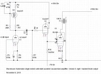
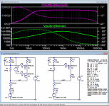
Attached, two simple gyrator circuits for anode loading, based on pmos devices, like users like Wavebourn and mogliaa have suggested.
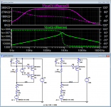
While it is possible to get decent AC impedances:
- left circuit (green trace) acts as an inductor only up to about 750 Hz, then impedance is capacitive. Is this the correct behaviour?
- right circuit (magenta trace) acts as inductor below 10 Hz, then seems like a CCS (not impressive impedance, though, below 400kohm) but no inductive reactance is present (V-I phase is zero). Again, is this correct?
As far as impedance is concerned, I’m able to achive higher impedance using CCS, and much flatter with frequency.
I’m suspecting errors or misunderstandings on my side, so I apprecite very much any correction or advice.
I’ve been reading quite a few (long) threads about gyrators, and most of them are old enough to (maybe) justify creating this new one. Sorry in advance, if this was not the most appropiate decision. Also, all simulations I’ve seen show the loaded stage gain vs frequency, not the impedance.
Attached, two simple gyrator circuits for anode loading, based on pmos devices, like users like Wavebourn and mogliaa have suggested.
While it is possible to get decent AC impedances:
- left circuit (green trace) acts as an inductor only up to about 750 Hz, then impedance is capacitive. Is this the correct behaviour?
- right circuit (magenta trace) acts as inductor below 10 Hz, then seems like a CCS (not impressive impedance, though, below 400kohm) but no inductive reactance is present (V-I phase is zero). Again, is this correct?
As far as impedance is concerned, I’m able to achive higher impedance using CCS, and much flatter with frequency.
I’m suspecting errors or misunderstandings on my side, so I apprecite very much any correction or advice.
Attachments
The p-channel 'gyrator' must have a source resistor, to program a set current: the high impedance you are searching for relies on having a stable current in the FET drain.
You can try improving the current source behaviour by replacing R1 (1MΩ) with a low impedance reference. You have to do that in a real, practical circuit, because leakage currents will cause big problems with high voltages across the 33MΩ resistor feeding the reference voltage.
Using cascoded depletion-mode N-channel FETs will give better results - models for the DN2540 are around on the web.
The p-channel 'gyrator' must have a source resistor, to program a set current
First of all, and just as a reference, I attached two of the examples by Wavebourn and Salas.
Aren't they very similar to the two circuits I posted?
Attachments
Anatoliy's schematic: has R4. You need this resistor!
Salas: 20K ref. Resistor vs. 1M in your circuit. Instead of a source resistor, Salas is using the source impedance of the top Pch FET. You must know exactly what you are doing, to make this work. Until then, it is better to use a resistor.
Nobody has 22 .. 33MΩ
When comparing the schematics of other designers, you need to know what their design objectives are!
If you are looking for increased dynamic impedance, why not simulate the suggestions I made for you?
And, you can try simulating those other circuits, and look at their dynamic impedance - it will be instructive.
Anatoliy's schematic: has R4. You need this resistor!
 Didn't I use it? It's R11 (top right, on my schematic). If you meant to say drain resistor, using one doesn't change things much.
And, you can try simulating those other circuits, and look at their dynamic impedance - it will be instructive.
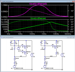
I already did. Just for reference, I attached them. The results don't really change my original question much.
Of course, I will try your sugestions, and appreciate them very much. Just I'm not trying to build the circuit, but to understand the behaviour in the ideal world
.Attachments
For a gyrator to work well as an active audio load it needs lots of open-loop gain thrown at it, since the impedance varies over at least 3 orders of magnitude across the audio spectrum, a more demanding application than in a bandpass filter for instance.
Thinking about it getting good gyrator performance across the audio band probably requires opamp levels of open-loop gain.
Thinking about it getting good gyrator performance across the audio band probably requires opamp levels of open-loop gain.
You could simulate Anatoliy's circuit, to see the output impedance of that (ac).
Here it goes. Circuit on the right/magenta. I plot V(out)/I. The inductive impedance is only >10Hz. Then, V-I are more or less in phase. It cannot be considered a simulated inductor.
About your other suggestions, I think I see what you tried to tell me:
- Please try adding a R11 to the other circuit - on the left side.
Circuit on the left/green. This raises the impedance on the low side, which is very nice, but degrades the circuit as a simulated inductor. The phase is only inductive well below 200 Hz. Maybe this is ok, but isn't a gyrator a simulated inductor?
- You can try improving the current source behaviour by replacing R1 (1MΩ) with a low impedance reference.
Even though I haven't built it, this dramaticaly increases the impedance, which again is nice. But the impedance is not inductive at all. V-I at the load are in phase.
- Using cascoded depletion-mode N-channel FETs will give better results
Yes. But again doesn't simulate an inductor, just a CSS or a voltage controlled CCS at best.
So, I'm not after getting as high impedance (dynamic resistance) as possible, but to try to understand the concept "gyrator" applied to audio gain stage load.
Attachments

For a gyrator to work well as an active audio load it needs lots of open-loop gain thrown at it, since the impedance varies over at least 3 orders of magnitude across the audio spectrum, a more demanding application than in a bandpass filter for instance.
Thinking about it getting good gyrator performance across the audio band probably requires opamp levels of open-loop gain.
I have a question about this. Are these circuits (this 'family' of circuits) actually
gyrators?
I have a question about this. Are these circuits (this 'family' of circuits) actually
gyrators?
No, by my understanding only the one I posted was a gyrator, a gyrator should be high impedance at AC and a low impedance at DC. In other words the DC current should depend on the load, not the gyrator itself.
The circuits shown in the first posts are no gyrators! A real gyrator is able to transform an impedance into the dual impedance (loading a gyrator with a capacitance shows inductive behaviour and vice versa). All these circuits called 'gyrator' as anode loads are more or less constant current sources to realize as high as possible AC impedances as anode loads (to obtain vertical load lines resulting in lowest distortions for triodes). Naming these circuits 'gyrator' is simply due to the fact that they have high AC impedance like an inductor of sufficient high value as anode load.
The circuits in post#1 show some inductive behaviour for a very limited frequency range due to the fact that there is some feedback established as the reference voltage for the CCS is derived via resistors from the CCS output. The capacitors used to smooth the reference voltage form a high pass leading to frequency dependant output impedance for low frequencies. If the reference is made stable with no feedback added, the output would become purely resistive for low frequencies and capacitive for high frequencies as soon as the parasitic transistor capacitances start playing a role.
The circuits in post#1 show some inductive behaviour for a very limited frequency range due to the fact that there is some feedback established as the reference voltage for the CCS is derived via resistors from the CCS output. The capacitors used to smooth the reference voltage form a high pass leading to frequency dependant output impedance for low frequencies. If the reference is made stable with no feedback added, the output would become purely resistive for low frequencies and capacitive for high frequencies as soon as the parasitic transistor capacitances start playing a role.
No, by my understanding only the one I posted was a gyrator
The circuits shown in the first posts are no gyrators!
I agree with that. From a purely theoretical point of view, they are not gyrators (as negative impedance converters). But in the audio world it seems common to call them that way.
Anyway, let's limit our discussion to circuits that simulate an inductor.
That's precisely the reason why I started this post: to clear if it is me that I'm not able to simulate that inductive behaviour, or I'm missing something.
I see these circuits (posted by me) as moderately good CCS (not great) but able to set the anode voltage, while a pure CCS cannot.
up to 1khz?Unless I'm blind, mine is the only one that allows you to set anode voltage and acts like an inductor.
Unless I'm blind, mine is the only one that allows you to set anode voltage and acts like an inductor.
Really? Talking about the two circuits I posted: the mosfet set a crude but real voltage reference, then the two resistors attached to the gate, which make a voltage divider, can be used to vary the anode voltage. Am I wrong?
Unless I'm blind, mine is the only one that allows you to set anode voltage and acts like an inductor.
Not being knowledgeable enough to analyze the circuit I have to ask in what way it acts like an inductor. Rising impedance with frequency? Swing above supply voltage?
Thanks
- Status
- This old topic is closed. If you want to reopen this topic, contact a moderator using the "Report Post" button.
- Home
- Amplifiers
- Tubes / Valves
- Gyrator impedance vs frequency