Did anybody try capacitors from Walmart? Looks like legit.
https://www.walmart.com/ip/Safety-Capacitor-Polypropylene-Film-0-33uF-275VAC-X2-MKP-10-Pcs/353328560
Those caps are excellent. Buy from eBay for 1/3 the price though.
I have no doubt the relay board would be ok for speakers just not tube power amplifiers
Small, 5 volt, SPST, normally open, reed relays are available for about $2.20 a throw from Mouser. “LittleFuse” brand. Circuit-board compact. Legs. 0.1 Ω maximum contact resistance (ON) (typical 0.030 Ω). Many GΩ open resistance. DC driving reed-coil is axially arranged, inducing no A/C EMF into reed. 7 mA holding current. Cute as a bug...
Make-before-break is also an option with the Arduino/Teensy approach: In synthetic terms, assuming one wanted to open relay 2 and close relay 4:
OUT 0b00000100 (earlier in testing, to set b₂ in sequence b₇ b₆-b₅-b₄-b₃-b₂-b₁-b₀) … then
… time elapses …
OUT 0b00010100 At transition, keeping ON b₂, but also ON b₄, then
OUT 0b00010000 a few milliseconds later, turning OFF b₂, ON b₄
… time lapses …
OUT 0b00011000 As user chooses b₃, leaving on b₄
OUT 0b00001000 a few milliseconds later, turning OFF b₄, ON b₃
… etc …
In many regards, this would be almost ideal - one has programmable control over how long the both ON momentarily condition exists; one is not required to wipe all capacitor-choices, because they're adjacent as in a rotary switch. Likewise, one can implement the "R" for random-choice trivially, which is nearly impossible with rotary switch. Further, with software control, one can choose to “hide the choice” completely when "R" is depressed. … time elapses …
OUT 0b00010100 At transition, keeping ON b₂, but also ON b₄, then
OUT 0b00010000 a few milliseconds later, turning OFF b₂, ON b₄
… time lapses …
OUT 0b00011000 As user chooses b₃, leaving on b₄
OUT 0b00001000 a few milliseconds later, turning OFF b₄, ON b₃
… etc …
Tell the truth, I cannot think of a better homebrew ABX/R testing regime.
Just Saying,
GoatGuy ✓
PS: also, with 4.7 MΩ precharge-bleed resistors as shown, the reed relays are not tasked with blocking 200+ volts, either. Only perhaps a few volts from the difference between the averaged capacitor blocking charge to the individual capacitor-under-test ("DUT" → device under test) actual instantaneous charge, at switching.
Last edited:
And… one could implement a "<" and ">" pair of buttons, to “go back” to the previous choice, then “double back” to the present choice. Even in "R" mode. Of course, with the 'light LED only on NEXT "R" choice' functionality (making 'double-blind' testing) the double-blind bit goes away with < and > buttons. 'Cuz you then will know the actual tested capacitors.
Oh, well … Still, it is useful functionality.
Lastly, since the Darjeeling Tea is beginning to kick in, I'm also thinking of a 'voting system'. A "V" button, which when held down (like a 'shift' on a keyboard) turns the DUT selector buttons into Vote-Score for the DUT. Dual functionality, and almost trivial in software to implement.
Hmmm… I'm also wondering whether one might (in software) assign fixed-but-a-random-shuffling of DUT choices to the numbered selection buttons. Y'know, shuffle the deck with the "S" button, then using buttons 1 thru 6 (and/or "R"), choose DUTs in any order the tester wants to choose them. But the assignment of DUT to button is hidden. The actual assignment could be displayed “at the end” on the USB attached tablet or computer. Decoding what the listener was actually voting upon.
Endless … useful … ideal?
GoatGuy ✓
ECWFE2J104P has a "P" on the end. Just as complete a number as what you posted. What you posted ECWFE2J104J
Mine has a "P" Yours has a "J" Probably different voltage.
Nope. As I said, it's the leads that are different (the "P" as you wrote it being incomplete). If you would have looked at the spec sheet it would have been obvious. Under "Explanation of part number". Can't believe I have to beat this dead horse to help you.
"P" vs "J"?
Easy peasy!!!! You guys are drowning in an glass of water!!!!
Tsk tsk .... you are welcome")
Easy peasy!!!! You guys are drowning in an glass of water!!!!
An externally hosted image should be here but it was not working when we last tested it.
Tsk tsk .... you are welcome
"P" vs "J"? Tsk tsk .... you are welcome
that made me laugh…
Endless … useful … ideal? [b said:Goat[/b]Guy ✓
Other options....
A log file of the whole session...
Automatic mode where the system runs each cap for 5 to 30 second intervals so the user only needs to relax and hit the vote button. They don't have to switch the cap. A lamp flashes each time the cap is auto switched. Votes get logged. Then at the end of voting through a whole symphony a winning cap is disclosed...
I think make before break eliminates a lot of problems with contact back EMF, pops, etc because nothing ever floats. the circuit never goes to open, a transition just momentarily puts double the capacitance in place but when the previous cap releases it drops back to the regular value. So a .2uf coupling amp momentarily puts .4uf in place during the transition. Also it would be much easier on the owners expensive amp.
It does sound like a unique piece of gear, at least I've never seen anything like it. You'd need some kind of safety lid over the capacitors that disconnects the insert leads automatically while loading in caps, so nobody gets a shock.
Last edited:
Other options....
A log file of the whole session...
Automatic mode where the system runs each cap for 5 to 30 second intervals so the user only needs to relax and hit the vote button. They don't have to switch the cap. A lamp flashes each time the cap is auto switched. Votes get logged. Then at the end of voting through a whole symphony a winning cap is disclosed...
I think make before break eliminates a lot of problems with contact back EMF, pops, etc because nothing ever floats. the circuit never goes to open, a transition just momentarily puts double the capacitance in place but when the previous cap releases it drops back to the regular value. So a .2uf coupling amp momentarily puts .4uf in place during the transition. Also it would be much easier on the owners expensive amp.
It does sound like a unique piece of gear, at least I've never seen anything like it. You'd need some kind of safety lid over the capacitors that disconnects the insert leads automatically while loading in caps, so nobody gets a shock.
Won't this still introduce a massive transient, especially if there is 250V across that cap?
Won't this still introduce a massive transient, especially if there is 250V across that cap?
No, not with the circuit diagram showing 4.7 MΩ resistors “in parallel” with each open switch contact. Such resistors allow each individual capacitor to slowly (i.e. “easy on the amplifier”) charge up to the average stage-to-stage DC blocking voltage. Then, as testing goes, switching from pre-charged capacitor to pre-charged capacitor elicits the least pop as 'this capacitor' and 'the next capacitor' equalize their charges, taken together.
GoatGuy ✓
Other options....
A log file of the whole session…
Automatic mode where the system runs each cap for 5 to 30 second intervals so the user only needs to relax and hit the vote button. They don't have to switch the cap. A lamp flashes each time the cap is auto switched. Votes get logged. Then at the end of voting through a whole symphony a winning cap is disclosed…
I think make before break eliminates a lot of problems with contact back EMF, pops, etc because nothing ever floats. the circuit never goes to open, a transition just momentarily puts double the capacitance in place but when the previous cap releases it drops back to the regular value. So a .2uf coupling amp momentarily puts .4uf in place during the transition. Also it would be much easier on the owners expensive amp.
It does sound like a unique piece of gear, at least I've never seen anything like it. You'd need some kind of safety lid over the capacitors that disconnects the insert leads automatically while loading in caps, so nobody gets a shock.
Logging - very useful and basically a modest set of program changes, both for the runtime code on the tablet / smartphone / laptop, and on the Arduino/Teensy microcode.
Automagic mode - An excellent tweak. Slave the selector buttons to 'vote mode'. Indeed … in many ways not much different from 'R'. But 'auto-R'. You vote, then immediately another random choice is made. Logging the whole while. I like it.
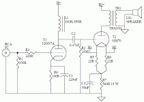
Safety - Hmmm… yes. I had envisioned that the top (light green background) sub-circuit, the “relay-and-capacitor” board, would actually be inside the chassis. Very close to the insertion point in the circuit. Thus, all caps would be “below deck”, so pretty safe, less their ability to short out other stuff close-by. Perhaps a simple plastic cover for each side would suffice!
Safety № 2 - the external controller is hooked by a narrow-gauge 'snake' to the internal relay board. With a battery pack, it could run stand-alone (or a wall wart, but I hate those things). Without that, it'd have to be tethered to a smartphone's USB, a tablet's USB or a laptop/PC's USB port for power. And logging. Everything in the Arduino/Teensy logic board runs at 5 volts, so is pretty darn safe.
Again, thank you for playing along, friend.
A life of being a whole-systems programmer influences my thinking.
Obviously…
-= GoatGuy ✓ =-
Logging - very useful and basically a modest set of program changes, both for the runtime code on the tablet / smartphone / laptop, and on the Arduino/Teensy microcode.
Automagic mode - An excellent tweak. Slave the selector buttons to 'vote mode'. Indeed … in many ways not much different from 'R'. But 'auto-R'. You vote, then immediately another random choice is made. Logging the whole while. I like it.
Safety - Hmmm… yes. I had envisioned that the top (light green background) sub-circuit, the “relay-and-capacitor” board, would actually be inside the chassis. Very close to the insertion point in the circuit. Thus, all caps would be “below deck”, so pretty safe, less their ability to short out other stuff close-by. Perhaps a simple plastic cover for each side would suffice!
Safety № 2 - the external controller is hooked by a narrow-gauge 'snake' to the internal relay board. With a battery pack, it could run stand-alone (or a wall wart, but I hate those things). Without that, it'd have to be tethered to a smartphone's USB, a tablet's USB or a laptop/PC's USB port for power. And logging. Everything in the Arduino/Teensy logic board runs at 5 volts, so is pretty darn safe.
Again, thank you for playing along, friend.
A life of being a whole-systems programmer influences my thinking.
Obviously…
-= GoatGuy ✓ =-
If this was such a good idea someone would have marketed it already.
Logging - very useful and basically a modest set of program changes, both for the runtime code on the tablet / smartphone / laptop, and on the Arduino/Teensy microcode.
Automagic mode - An excellent tweak. Slave the selector buttons to 'vote mode'. Indeed … in many ways not much different from 'R'. But 'auto-R'. You vote, then immediately another random choice is made. Logging the whole while. I like it.
Safety - Hmmm… yes. I had envisioned that the top (light green background) sub-circuit, the “relay-and-capacitor” board, would actually be inside the chassis. Very close to the insertion point in the circuit. Thus, all caps would be “below deck”, so pretty safe, less their ability to short out other stuff close-by. Perhaps a simple plastic cover for each side would suffice!
Safety № 2 - the external controller is hooked by a narrow-gauge 'snake' to the internal relay board. With a battery pack, it could run stand-alone (or a wall wart, but I hate those things). Without that, it'd have to be tethered to a smartphone's USB, a tablet's USB or a laptop/PC's USB port for power. And logging. Everything in the Arduino/Teensy logic board runs at 5 volts, so is pretty darn safe.
Again, thank you for playing along, friend.
A life of being a whole-systems programmer influences my thinking.
Obviously…
-= GoatGuy ✓ =-
Thinking more the safety mode needs to reinstall a "default" capacitor. So if the user is allowed to load up to 5 DUT capacitors, they must also always load a default cap. When the lid is opened, it simply always inserts the default cap and also disconnects the DUT bus bar. This way they can freely change the DUTs it's disconnected and the amp is still playing fine on the default cap.
The Cornell-Dubilier 942C series is an excellent cap, as good as any boutique cap I've tried, if not better. Try to 1000VDC rating or higher, they sound better than the 600VDC.
This has been my experience as well. Although not as good as my teflons but those cost ten times more!
No, not with the circuit diagram showing 4.7 MΩ resistors “in parallel” with each open switch contact. Such resistors allow each individual capacitor to slowly (i.e. “easy on the amplifier”) charge up to the average stage-to-stage DC blocking voltage. Then, as testing goes, switching from pre-charged capacitor to pre-charged capacitor elicits the least pop as 'this capacitor' and 'the next capacitor' equalize their charges, taken together.
GoatGuy ✓
Alright, that makes sense. Sorry, I didn't realize those resistors were there. Pays to look at the schematic.
If this was such a good idea someone would have marketed it already.
You'd be surprised what the high end audiophiles are buying now. One of the popular booths at Axpona this year was a vacuum tube tracer, the eTracer. Yes regular audiophiles, with no experience in electronics, are tracing and matching tubes themselves. Printing out the traces, this one has a computerized load line feature. People can only buy $500 power cords and $1000 interconnects so many times, if they think their coupling caps are not the best, they will be looking for gear to test them! I say build it them rent a booth at Axpona!
You'd be surprised what the high end audiophiles are buying now. One of the popular booths at Axpona this year was a vacuum tube tracer, the eTracer. Yes regular audiophiles, with no experience in electronics, are tracing and matching tubes themselves. Printing out the traces, this one has a computerized load line feature. People can only buy $500 power cords and $1000 interconnects so many times, if they think their coupling caps are not the best, they will be looking for gear to test them! I say build it them rent a booth at Axpona!
The eTracer is exciting because it is the only option that isn't astronomically expensive. I'd be willing to bet that most of the people looking at it at that show were more involved in vacuum tubes than just owning an amplifier. The cost of a working Tektronix 576 or 577 (about the only other option since they can do vacuum tubes with an adapter) is the reason why so many people are excited about the eTracer.
I wouldn't be surprised if some of the people looking at the eTracer were people who were just desperately hoping they could mod it to do transistors.
Something off topic or not...
In case anyone is interested, I have also replaced Bennic's cheap cement resistor with Mills MRA5 5 watts in KEF Q100 crossover.
[PDF] https://hfc-fs.s3-eu-west-1.amazonaws.com/s3fs-public/mills_data_0.pdf
Looking for a new pair of 0.22uf coupling caps.

Very great improvement!
In case anyone is interested, I have also replaced Bennic's cheap cement resistor with Mills MRA5 5 watts in KEF Q100 crossover.
[PDF] https://hfc-fs.s3-eu-west-1.amazonaws.com/s3fs-public/mills_data_0.pdf
Looking for a new pair of 0.22uf coupling caps.
Very great improvement!
You'd be surprised what the high end audiophiles are buying now. One of the popular booths at Axpona this year was a vacuum tube tracer, the eTracer. Yes regular audiophiles, with no experience in electronics, are tracing and matching tubes themselves. Printing out the traces, this one has a computerized load line feature. People can only buy $500 power cords and $1000 interconnects so many times, if they think their coupling caps are not the best, they will be looking for gear to test them! I say build it them rent a booth at Axpona!
Why does any of this suprise anyone. The list of useless audiophool tweaks is enormous, ranging from ridiculous to not enough Os in stooopid. And the more expensive that box of nothing is, the more its sought after. This thread is the perfect example of the self delusion that goes on. Right after reason and proof,( numbers and dble blind testing) : SYclotron Audio | Why are people obsessed with coupling caps?
The phools are at it again.
"If you have room inside the amps:
2x FT-3 0.1 UF 600V 5% Capacitor for Best audio. A strong matched pair. | eBay"
Look at those caps, what a joke!
Last edited:
You'd be surprised what the high end audiophiles are buying now. One of the popular booths at Axpona this year was a vacuum tube tracer, the eTracer. Yes regular audiophiles, with no experience in electronics, are tracing and matching tubes themselves. Printing out the traces, this one has a computerized load line feature. People can only buy $500 power cords and $1000 interconnects so many times, if they think their coupling caps are not the best, they will be looking for gear to test them! I say build it them rent a booth at Axpona!
Where I used to work we had a salesman that loved to sell interconnects, power cords and such at very high prices. I think there needs to be a point where credibility enters the scene again. We seem to be able to sell polished rocks and polished turds without any problems and the only concern is the almighty dollar, or pound or whatever.
Sure you can sell a machine to match tubes but do you also tell the individual how many hours he can expect his matched tubes to stay perfectly matched? Yup, you can build a device so that you can fool yourself into thinking that a $100 capacitor sounds better than a $2.00 one. Congratulations, you have sunk to a new low.
- Status
- This old topic is closed. If you want to reopen this topic, contact a moderator using the "Report Post" button.
- Home
- Amplifiers
- Tubes / Valves
- On the cheap..Best coupling cap