The capacitance of the C in a practical RC coupling network (example 0.1uF) is 1000 times more than a miller effect capacitance of 100pF, which is even more than the miller effect of a 300B ((u+1) * Cgp). u = 3.85, and Cgp = 15pF (72.75 pF)
The only worry you have with miller capacitive effect is at high frequencies, and only if
the impedance from the driver is too high versus the capacitive reactance of the miller effect capacitance. 73pF is 109k Ohms at 20 kHz. But the 6SN7 plate resistance of
7,700 Ohms is so low (far far less than 100k). Nothing to worry about here either.
With an RC network of 0.1uF and a grid resistor of 200k Ohms, the -3 dB network is 8 Hz.
That is only -1 dB at 16 Hz.
Or, instead, with 0.1uF and a grid resistor of 100k, it will be -3dB at 16 Hz, and only -1 dB at 32 Hz.
Well, am I worried by -1 dB at 32 Hz?
No I am not, my speakers do not even come close to going that low.
Nothing to worry about here either.
I would say that any 300B that I would use, and that is self biased, can work with a 200k grid resistor.
And if I wanted to be super conservative, I could use a 100k grid resistor.
Any 300B that will not work there, needs to either be thrown in the garbage can,
or donated to the museum to be looked at with wonder (why was it Gassy).
Do you mean mixed bias?
Split Williamson Amplifier & Class-G
That's very useful to me, euro21. Many thanks.
The only worry you have with miller capacitive effect is at high frequencies, and only if
the impedance from the driver is too high versus the capacitive reactance of the miller effect capacitance. 73pF is 109k Ohms at 20 kHz. But the 6SN7 plate resistance of
7,700 Ohms is so low (far far less than 100k). Nothing to worry about here either.
Yes. I got my highs and lows mixed up. I need to get out more.
One thing I've thought about is using a 6SN7 cascade direct coupled between the input and driver stages but using a 2:1 step down transformer between the driver stage and the 300B. That results in the plate resistance of the 6SN7 being cut to 1/4 and losing half the amplification of the driver stage, but two 6SN7's in cascade have a lot of gain anyway. You could also keep your 1:1 ratio Hammond 124 and use something like a 6EM7.
Could you take a look at my circuit and suggest why it is not working? I bought 6 IXCP10M90S CCSs and I can not get even one of them to draw any current at all. I've checked the wiring over and over again and I cannot see anything wrong. I am aiming for 6mA, but nothing comes through. I have substituted a 22K resistor to check if the amp wiring is OK, and yes it is. Could it be possible that I bought a bad batch? Many thanks.I often use a 900V rated IXYS current source in the plate load of the driver tube. The grid resistor of the output stage is a lower impedance than the current source is, but the parallel impedance is high enough that I get lots of gain (almost u), and lots of voltage swing for the grid of the output tube. The high impedance load across the complete audio frequency range gives low distortion of the driver tube.
Attachments
The voltage is 339V, just one Volt less than HT. No, the tab, as they call it is well away from all other parts.What is the voltage at pin 5 (plate) of 6SN7?
Is the heat slug of IXCP10M90S (High voltage) touching anything?
Thanks for the suggestion. I have just changed it to 330R - it hasn't made any difference. No current at all coming through. I just can't believe that all 6 are faulty. I bought them on eBay from a source in London England that has a 99.3% positive feedback rating. Maybe I'll buy some from Mouser or Digikey who take deliveries direct from the manufacturer.Try changing the 620R up and down by 200R or so and see what happen. In my previous application, I used an 600R on an 6SN7 driver as well. I recalled I had to change that reference R by some to get it to work.
If it was good with RC coupling, then magnetic fields from the power transformer to the input tube is not the problem.
Is your chassis (magnetic) steel?
That couples power transformer fields to the interstage transformers.
Rotational Orientation helps, but the magnetic coupling of the steel chassis is still there.
Is your chassis (magnetic) steel?
That couples power transformer fields to the interstage transformers.
Rotational Orientation helps, but the magnetic coupling of the steel chassis is still there.
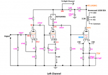
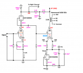
I have now successfully implemented the IXCP10M90S CCS as the plate load for the 6SN7 which drives the 300B. The result is phenomenal. GoatGuy is correct with his estimate of the dynamic resistance of the IXCP10M90S - it is certainly around 1MΩ at 6mA. I am using a 330K grid resistor on the 300B (yes, I know I'm living dangerously). This gives the 6SN7 a plate load of 248K - as near as dammit to a straight line.Here is the 900V current source that I use as the plate load:
https://ixapps.ixys.com/DataSheet/DS98729A(IXCP-CY10M90S).pdf
That data sheet has lots of info.
You can see an example of the plate current for a 300 Ohm sense resistor, the plate current will be about 9 mA.
You can have 250V across the 6SN7, plus 150V across the IXYS current source (400V B+, but can try 350V with 200V across the 6SN7, and a cathode resistor of about 680 Ohms to get the self bias volts at about 6V). Bypass the self bias resistor with 100 uF.
That way you can get lots of volts of linear signal out of the 6SN7.
With 400V B+, the self bias needs to be about 9V, so use a 1k cathode resistor to start. Bypass the 1 k with 100 uF to start.
The IXYS dissipation will be 9mA * 150V = 1.35 Watts, use a small heat sink, or a rubber insulator and attach to the chassis. IXYS, rubber, chassis (use insulating washers that have the shoulder to keep the mounting screw from touching the chassis).
I've measured the gain of the stage, and it is 19.8 - incredibly close to mu, but the really great aspects to this are the available voltage swing and linearity. I still need to fine-tune the bias and HT. I how have 2 Hammond 126C ISTs for use as doorstops. That was my first experience with ISTs, but I'm not dismissing them altogether - I can't see any need for them in this sort of simple 300B amplifier, now that I have been introduced to the world of Constant Current Sources.
To drive my 300Bs to a theoretical 8 Watts (7 Watts is more realistic), I need about 57 Volts RMS (80V Peak). With a gain of 20, the input to the 6SN7 driver would need to be 2.85 Volts RMS. This is well within the capabilities of all my pre-amps, and so the first half of the 6SN7 is now unused, just wasting heater Watts.
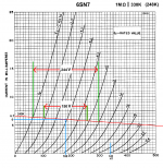
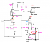
I've drawn out the operating conditions on the 6SN7 curves, and am also including the circuit of my new amplifier version in all its simplicity. It sounds just fine even with cheap Liuzhu 300Bs. Driver stage linearity enables the tonal characteristics of the 300Bs to be heard, without too much driver distortion diluting it.
Attachments
Last edited:
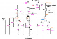
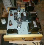
I became so enthusiastic about the IXCP10M90S, that I have now replaced the 1K cathode resistor on the 300Bs with this CCS device. I set the Ia to 72 mA and with the voltages shown on the schematic, I can run it to exactly 8 Watts before clipping. The 2 CCSs are mounted on the underside of the 2.1K/Watt heatsinks which are in the spot where the Hammond 126C interstage transformers once were. I have put in two sets of test points - one for the Ia across a 10 Ohm temperature-stable, 0.1% tolerance resistor, and the other monitoring the voltage on the cathode, to determine the grid bias on the 300B. I've listened to it most of the day with JJs at medium volume, and I'm very happy with the way it sounds. The heat sinks are always under 50º C even when the room heats up to about 25.
I can swap in any 300B tube, including my cheap Liuzhous and Golden Dragons whose emissions vary wildly, and be guaranteed an Ia of 72mA. But of course, the bias will be different for each tube. Some interesting experiments lie ahead.
I can swap in any 300B tube, including my cheap Liuzhous and Golden Dragons whose emissions vary wildly, and be guaranteed an Ia of 72mA. But of course, the bias will be different for each tube. Some interesting experiments lie ahead.
Attachments
Last edited:
post # 76.
Looks great!
One thing I notice is that the choke is oriented magnetically the same as the output transformers. At least it is offset toward the front, and the output transformers to the back.
You might try rotating the choke 90 degrees if you still have hum.
With steel chassis, I have sometimes raised the choke and output transformers off the chassis by using 1/4 inch non-magnetic spacers.
Last edited:
Since I took out the Hammond interstage transformers, and replaced them with your suggestion of using the IXCP10M90S instead, the hum pickup has disappeared. Taking out the first 6SN7 stage stopped all hum pickup in the driver section. I have more than enough gain and voltage swing (200V P-P) from the one half of the tube. All my pre-amps can deliver at least 10 Volts RMS signal.post # 76.
Looks great!
One thing I notice is that the choke is oriented magnetically the same as the output transformers. At least it is offset toward the front, and the output transformers to the back.
You might try rotating the choke 90 degrees if you still have hum.
With steel chassis, I have sometimes raised the choke and output transformers off the chassis by using 1/4 inch non-magnetic spacers.
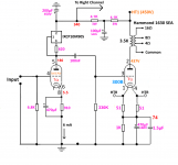
As you can see, I have also put the IXCP10M90S in the cathodes of the 300Bs - I'm still measuring and listening, but things look promising. Many thanks for your help, and I will post updates on any developments, good or bad.
A WARNINGAs you can see, I have also put the IXCP10M90S in the cathodes of the 300Bs - I'm still measuring and listening, but things look promising. Many thanks for your help, and I will post updates on any developments, good or bad.
I have discovered a serious problem with the implementation of the IXCP10M90S in the cathode circuit of the 300B. On power-up, the current through the tube shoots up to 110mA, and then drops back to its regulation 72mA after about 1.5 seconds. I have traced the cause of this to the the time it takes to charge the 470μF cathode bypass capacitor. The resistance of the CCS drops down very low just after power-on, as the filament comes up to temperature, to do its job of maintaining the Ia at 72mA, thereby robbing the bypass cap of the ability to charge. The voltage across the combination drops, and therefore the grid bias. 470μF is way to large, so I will substitute a 47μF cap. This still gives me a low break-point of about 3.5Hz, and the gain should drop by about only 0.7dBs at 40Hz. I don't know why I put such a large bypass cap there in the first place, but reducing it by a factor of 10:1 should solve the problem.
Attachments
Last edited:
Take a look at Bartola Valves website - Ale Moglia. Read up on using his gyrator with a 6e5P or 6e6P as driver for your 300b. And also look at using a SIC diode combination in the cathode. I'm using his suggestion of the C3D02060F and it sounds great. You'll get around .85v per diode.
Attachments
- Home
- Amplifiers
- Tubes / Valves
- Problem using Hammond 126C IST