Hello friends. I recently bought a pair of Hammond 126C interstage transformers to couple my 6SN7/300B SET. Using the circuit attached, I am getting 63 Volts RMS drive for the 300Bs with a very clean looking waveform down to 40 Hz. This is way more than adequate for the 300B. My problem is that I am getting an ugly waveform on the amplifier output, which is originating in the 6SN7 driver stage. (I have proven the source by experimentation). The offending signal is about 15 millivolts P-P at 50Hz with a strong 3rd harmonic component. My line frequency is 50Hz, so I am tempted to think it is mains supply pickup. This ugly beast was not present in the output when I was using RC coupling. Has anyone else experienced this problem with the 126C? I'd very much appreciate any suggestions.


Yes, I've tried that, and various combinations of phase. I've also tried using the 126C as a choke and capacitor-coupling the 6SN7 plate to the 300B grid. The waveform increased in level.Did you try to reverse the output wiring from 126C?
Its clearly picking up magnetic interference from the mains transformer. That mass of EI iron core without good mu-metal shielding is going get magnetic pickup, and due to its size its range will be large - magnetic fields fall off with distance sharply once those distances become larger than the magnetic components themselves. You may be able to decrease the coupling by re-positioning or turning one or both transformers.
Yip, it's connected. It's there in case the 126C goes open circuit and destroys the 300B. I'm going to reduce it to 56K and see what happens.You sure the 330k grid resistor is connected?
I think you are right. It will be easier to shield the mains transformer with some mu metal than both 126C interstages. The 6SN7 with the Hammond 126C drives the 300B really well, giving a clean 63 Volts RMS - way more than is required by the 300B. I'm determined to get this sorted, and then I will use Rod Coleman's Fixed Bias Regulator to eliminate the 74 Volt drop on the cathode resistor.Its clearly picking up magnetic interference from the mains transformer. That mass of EI iron core without good mu-metal shielding is going get magnetic pickup, and due to its size its range will be large - magnetic fields fall off with distance sharply once those distances become larger than the magnetic components themselves. You may be able to decrease the coupling by re-positioning or turning one or both transformers.
Last edited:
It will be easier to shield the mains transformer with some mu metal than both 126C interstages.
It is easiest at first to turn one 126C 90 degrees and see if that will solve the problem.
Can you show the lay-out of your amplifier ?
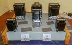
Here is the layout without tubes. I have just removed the 126C from the chassis on leads and pulled it away from the amp. Whereas increasing the distance makes very little difference, It's orientation, even away from the amp, reduces it by 50%. The orientation that works best is at a ridiculous 45 degrees in both the vertical plane and the horizontal plane (away from the amp). It must be picking up magnetic fields from mains cables in the vicinity. I have also covered it with a steel paint tin, but this makes absolutely no difference.It is easiest at first to turn one 126C 90 degrees and see if that will solve the problem.
Can you show the lay-out of your amplifier ?
Attachments
If moving the IT does not offer any immediate clues, please consider the susceptibility of the driver valve, too.
The 5V on the cathode shows that the 6SN7 driver is running at 5mA. Regardless of the anode voltage, this means an effective anode slope resistance of about 10KΩ. This might be considered a high value for a driver, and more importantly, it gives only a weak control of noise-EM fields. If the bypass cap is old or has high ESR, the effect is degraded a little more.
I don't think the 6SN7 (ra=10KΩ) will ever succeed as a driver of a 10KΩ IT. This is really a job for a power tube. But many good candidates prefer more current than the 15mA allowed by the 126C; some compromise will be needed.
Possible solution: Russian 4P1L in triode connexion, running 250V 15mA may be worth a look - the ra should easily be low enough.
Thanks for that, Rod. I will certainly consider all you have suggested.If moving the IT does not offer any immediate clues, please consider the susceptibility of the driver valve, too.
The 5V on the cathode shows that the 6SN7 driver is running at 5mA. Regardless of the anode voltage, this means an effective anode slope resistance of about 10KΩ. This might be considered a high value for a driver, and more importantly, it gives only a weak control of noise-EM fields. If the bypass cap is old or has high ESR, the effect is degraded a little more.
I don't think the 6SN7 (ra=10KΩ) will ever succeed as a driver of a 10KΩ IT. This is really a job for a power tube. But many good candidates prefer more current than the 15mA allowed by the 126C; some compromise will be needed.
Possible solution: Russian 4P1L in triode connexion, running 250V 15mA may be worth a look - the ra should easily be low enough.
I have decided to persevere with the 6SN7, as it gives good drive for the 300B with the Hammond 126C interstage. I have to play the hand I was dealt. Altering the design at this stage would involve a complete rebuild of the amplifier and undo months of construction work on the steel chassis.
A Mu metal screening can would seem to be the only practical solution. I will make it from hard plastic and line the interior with Ultraperm 80 Mu Metal shield. LINK
A Mu metal screening can would seem to be the only practical solution. I will make it from hard plastic and line the interior with Ultraperm 80 Mu Metal shield. LINK
Is your B+ choke input?
Or, if it is cap input, is the input cap a relatively small capacitance?
Both of those have large magnetic hum fields from the choke.
Of course, with cap input, do not make the cap to large or a tube rectifier may get
hot, spark, etc., and solid state diodes may have so much Isquared * R current that the power transformer secondary overheats.
Instead of changing the B+ circuit, then check these:
I ask, because your B+ choke is in the same orientation as the interstage transformers.
Turn your Choke 90 Degrees, and see if the offending hum gets smaller.
I have used EI SE transformers, and push pull EI interstage transformers, and two winding auto transformer phase splitters with EI cores.
They all were susceptible to magnetic hum pickup.
I also used Lundahl interstage transformers (they did not pick up as much hum from power transformers and chokes).
But now I only use RC coupling.
No hum. Most of my SE and push pull amps have less than 100uV of hum at the 4 Ohm output with a 8 Ohm load resistor attached.
I often use a 900V rated IXYS current source in the plate load of the driver tube. The grid resistor of the output stage is a lower impedance than the current source is, but the parallel impedance is high enough that I get lots of gain (almost u), and lots of voltage swing for the grid of the output tube. The high impedance load across the complete audio frequency range gives low distortion of the driver tube.
Interstage transformers have lower impedance at bass frequencies (inductance), and lower impedance at high frequencies (distributed capacitance).
I generally use self bias on the output tube(s), and a grid resistor that is 1/2 or less than the maximum resistance spec for self bias operation. That way, the output tubes do not go into thermal run-away.
Just some of what I do.
I think a 6SN7 plate loaded with a 900V IXYS current source has plenty of voltage swing to work with RC coupling to drive a 300B.
I do not use the 450V IXYS current sources because most of my amp B+ rises close to 500V until the tubes warm up.
That means the IXYS is at more than 450V, and is trying to charge the cap of the RC coupling, until the tubes warm up (so the transient voltage across the IXYS part exceeds the 450V rating).
Last edited:
Oh, is the chassis Steel?
Magnetic forms of steel and interstage transformers is not a good thing.
There are some stainless steel that have very low to no magnetic properties.
Hello 6A3sUMMER. Many thanks for your two replies to my thread. You've certainly put a lot of effort into helping fix my problem, for which I am most grateful. I will do my best to respond to all the points you made.
The HT PSU is capacitor input. I'm using 110μF, which is more than twice the maximum recommended for the 5U4G, but I used a 1976 NOS Russian 5Ц3C military grade equivalent. They are supposed to be bullet-proof. The B+ 10H choke is in that orientation due to space limitations and maybe I didn't put enough thought into it. The addition of the 126C interstage was an afterthought because my 6SN7 could not drive the 300B to full output without considerable rounding of its waveform as it approached cutoff. BTW, the original RC setup was whisper-quiet.
I have considered using a Lundahl or another more expensive C-Core or R-Core instead, but you have put me off the idea with your experience of interstage transformer hum pickup generally. I have even removed the 126C from the chassis (steel) and brought it away on long leads, then tried orienting it in my hand, but no total success, just a 50% reduction in hum pickup at a 45 degree rotation in both horizontal and vertical planes. I can't rule out that my hand could have been inducing hum too though or there is the possibility that hum is being picked up from the maze of cables nearby.
You have tempted me to go back to RC coupling again with talk about using a CCS. I know absolutely nothing about these solid-state devices, but I am about to spend today getting up to speed on them. I wonder what the load-line would look like when using one of these. Do they take the place of the plate resistor?
You give me encouragement to go back to the original method I was using. Would you have a schematic of a 6SN7 driver which uses a CCS device in the plate? I'd really like to see an example of its use driving a 300B.
Last edited:
1. Keep the interstage transformers, choke, and power transformer oriented-upright like you originally had them. Do not lie one of them down.
But now, rotate just the choke 90 degrees (either clockwise or anti-clockwise) as viewed from the top (then the choke will be oriented the same as the power transformer).
That way, both the choke and the power transformer will be magnetically oriented 90 degrees with respect to the interstage transformers.
If you have an aluminum chassis, that should work fairly good to reduce magnetically induced hum.
I have had hum problems with interstage transformers on a steel chassis. Hum could only be reduced, not eliminated.
2. Here is the 900V current source that I use as the plate load:
https://ixapps.ixys.com/DataSheet/DS98729A(IXCP-CY10M90S).pdf
That data sheet has lots of info.
You can see an example of the plate current for a 300 Ohm sense resistor, the plate current will be about 9 mA.
You can have 250V across the 6SN7, plus 150V across the IXYS current source (400V B+, but can try 350V with 200V across the 6SN7, and a cathode resistor of about 680 Ohms to get the self bias volts at about 6V). Bypass the self bias resistor with 100 uF.
That way you can get lots of volts of linear signal out of the 6SN7.
With 400V B+, the self bias needs to be about 9V, so use a 1k cathode resistor to start. Bypass the 1 k with 100 uF to start.
The IXYS dissipation will be 9mA * 150V = 1.35 Watts, use a small heat sink, or a rubber insulator and attach to the chassis. IXYS, rubber, chassis (use insulating washers that have the shoulder to keep the mounting screw from touching the chassis).
Last edited:
1. Keep the interstage transformers, choke, and power transformer oriented-upright like you originally had them. Do not lie one of them down.
But now, rotate just the choke 90 degrees (either clockwise or anti-clockwise) as viewed from the top (then the choke will be oriented the same as the power transformer).
That way, both the choke and the power transformer will be magnetically oriented 90 degrees with respect to the interstage transformers.
If you have an aluminum chassis, that should work fairly good to reduce magnetically induced hum.
I have had hum problems with interstage transformers on a steel chassis. Hum could only be reduced, not eliminated.
2. Here is the 900V current source that I use as the plate load:
https://ixapps.ixys.com/DataSheet/DS98729A(IXCP-CY10M90S).pdf
That data sheet has lots of info.
You can see an example of the plate current for a 300 Ohm sense resistor, the plate current will be about 9 mA.
You can have 250V across the 6SN7, plus 150V across the IXYS current source (400V B+, but can try 350V with 200V across the 6SN7, and a cathode resistor of about 680 Ohms to get the self bias volts at about 6V). Bypass the self bias resistor with 100 uF.
That way you can get lots of volts of linear signal out of the 6SN7.
With 400V B+, the self bias needs to be about 9V, so use a 1k cathode resistor to start. Bypass the 1 k with 100 uF to start.
The IXYS dissipation will be 9mA * 150V = 1.35 Watts, use a small heat sink, or a rubber insulator and attach to the chassis. IXYS, rubber, chassis (use insulating washers that have the shoulder to keep the mounting screw from touching the chassis).
There's a good amount of info there for me to consider. I've been up since early morning, gradually getting the hang of these devices. I'm very encouraged. Looks like the 900V version is very affordable at about $10 each. I'll plough away at the learning for the rest of the day; hopefully by evening time I should be fully up to speed. If I can't kill the hum, this is the way I'll go. Thanks again.
PS. I have just gotten a very snotty reply from Per Lundahl when I asked him about using the LL1660 in my amplifier. He replied that "Lundahl were transformer manufacturers, and not tube amp designers". I suppose he never heard of application notes.
Last edited:
You can have 250V across the 6SN7, plus 150V across the IXYS current source (400V B+, but can try 350V with 200V across the 6SN7, and a cathode resistor of about 680 Ohms to get the self bias volts at about 6V). Bypass the self bias resistor with 100 uF. That way you can get lots of volts of linear signal out of the 6SN7.
I wonder what the load line would look like when using the CCS. Will it be almost horizontal? I see that the spec sheet says that it has an Rak of 58K. Does that mean that the slope of the load line will be for 58K?
The IXYS data sheet shows a graph of Rak versus temperature.
You will note that Vgk is 0.
I think with Vgk adjusted to give lower currents, the Rak is much higher.
That has been my experience.
I quoted the 300 Ohm current sense resistor, as in the data sheet.
The more the resistance, the less the current. The voltage drop is > the 0V, so there is a higher Rak.
I have one of the IXYS with 410 Ohms, it sources about 6.7mA.
I measured the stage gain, and compared it to the tube u spec. At that time, I used the tube rp, the next stage Rg, and did a rough calculation to estimate the Rak to be far in excess of 100k.
Yes, the idea is to get a fairly flat load line (like 100k or greater). You should get close to u of the 6SN7. If that is not enough gain, you can use the other triode in the 6SN7. If that extra stage has too much gain, just set the ratio of the cathode self bias resistor versus the plate load resistor and next stage Rg, to reduce the gain of the extra stage. Do not bypass the extra (input) stage's self bias resistor.
I hope that helps.
PS. I have a Teak tape recorder with auto reverse, it needs to be fixed . . . someday.
I rented a couple of EV omnidirectional dynamic mikes and recorded a choir that I was in. (in the late 60s).
I also recorded a few LPs.
I also have a Sony tape recorder, it also needs work (rollers and belts?).
I have almost 100 pre-recorded tapes, I guess I need to get busy fixing the recorders.
Last edited:
The IXYS data sheet shows a graph of Rak versus temperature.
You will note that Vgk is 0.
I think with Vgk adjusted to give lower currents, the Rak is much higher.
That has been my experience.
I quoted the 300 Ohm current sense resistor, as in the data sheet.
The more the resistance, the less the current. The voltage drop is > the 0V, so there is a higher Rak.
I have one of the IXYS with 410 Ohms, it sources about 6.7mA.
I measured the stage gain, and compared it to the tube u spec. At that time, I used the tube rp, the next stage Rg, and did a rough calculation to estimate the Rak to be far in excess of 100k.
Yes, the idea is to get a fairly flat load line (like 100k or greater). You should get close to u of the 6SN7. If that is not enough gain, you can use the other triode in the 6SN7. If that extra stage has too much gain, just set the ratio of the cathode self bias resistor versus the plate load resistor and next stage Rg, to reduce the gain of the extra stage. Do not bypass the extra (input) stage's self bias resistor.
I hope that helps.
PS. I have a Teak tape recorder with auto reverse, it needs to be fixed . . . someday.
I rented a couple of EV omnidirectional dynamic mikes and recorded a choir that I was in. (in the late 60s).
I also recorded a few LPs.
I also have a Sony tape recorder, it also needs work (rollers and belts?).
I have almost 100 pre-recorded tapes, I guess I need to get busy fixing the recorders.
Thanks for that. I'm going to run it at 6mA, so I'll see what I get.
I'm a total tape recording nut. Over the last 4 years, I have restored, electronically and mechanically, a Studer A80-R Master studio recorder, three Studer B67 studio machines, two Nagra IV-S portable broadcast machines and three Uher 4400-S IC portables. I have transcribed thousands of valuable master tapes.
What a pity you live so far away - I could transcribe your 1960s tapes. A word of caution: your tapes will have degraded both physically and magnetically over the years. You will need to play and handle them with extreme care to avoid the effects of oxide-shed. Also, if you don't wind them soon, they will print-through and ruin the material - unfortunately, this may have already started to occur. It needs to be done on a machine that is well set up mechanically and preferably does not have static tape lifters, only all rollers. It depends on which tape stock you used originally. BASF was the best of the professional makes, AGFA and Racal were the worst. Any others might not have preserved the original material completely intact.
- Home
- Amplifiers
- Tubes / Valves
- Problem using Hammond 126C IST