If you are looking for an anode load that presents a high impedance to the valve, and a low impedance to the load, Ale's PCB for his « µ-follower » is a good solution, and will offset the shortcomings of the 6SN7 in this position.
Gyrator PCB – Bartola(R) Valves
These will drive a 300B very well, and the lower output impedance is a big plus.
Gyrator PCB – Bartola(R) Valves
These will drive a 300B very well, and the lower output impedance is a big plus.
Great, thanks Rod. I'll have a look now.If you are looking for an anode load that presents a high impedance to the valve, and a low impedance to the load, Ale's PCB for his « µ-follower » is a good solution, and will offset the shortcomings of the 6SN7 in this position.
Gyrator PCB – Bartola(R) Valves
These will drive a 300B very well, and the lower output impedance is a big plus.
1. As a general rule, never put 2 current sources in series.
For example, if one current source has more current than the other current source, then almost all of the voltage will be across the current source that tries to draw less current.
And what happens if the current sources current is exactly matched at one temperature. But then what happens if the temperature changes: one of their currents can now be different than the other ones new current at the new temperature?
Not good, again, almost all the voltage is now across the current source that tries to draw a little less current.
2. A 6SN7 has a plate resistance, rp, of 7700 Ohms.
A 300B has a grid to plate capacitance of 15pF.
A 300B has a u = 3.85 (but the actual gain will be less than u when driving the output transformer).
Lets allow for the gain to be = u (worst case Miller Capacitance effect).
15 pF x 3.85 = 57.75 pF.
The 300B grid to filament capacitance is 8.5 pF.
57.75 pF + 15 pF + 8.5 pF = 81.25pF worst case.
Xc =1/(2 * pi * f * c)
(Xc * 2 * pi * c) = 1/f
f = 1/(Xc * 2 * pi * c)
At Xc = rp, we have the - 3dB point due to the effective 300B grid capacitance.
7700 Ohms = rp = Xc.
f = 1/(7700 * 2 * pi * c)
f = 254 kHz
The 6SN7 plate impedance, rp, is plenty low enough to drive a 300B to 254 kHz.
(Oh, the -1 dB point will be at 127 kHz, lots better than most tweeters).
You can see several successful commercial amplifiers that drive a 300B with a 6SN7 (no special added circuitry).
I have to ask the question: what are the audible shortcomings of using a 6SN7 on those commercial amplifiers that have good reviews . . .
and that have many happy listening owners?
Simple circuits work very good.
Your mileage may vary (There are not too many SE output transformers that have 254kHz bandwidth, and if they do, they are more expensive than I can afford).
I will admit, a low impedance drive to the grid of a 300B can in some cases draw grid current. At that point, you can get more output power.
But the Western Electric original data advises not to draw grid current.
Need more power? Use a more powerful output tube.
Last edited:
The question of suitability of 6SN7 driving impedance chiefly affects the IT solution: 10KΩ triode driving a 10KΩ primary gives poor performance, because the triode thinks the load is too low (enters the worst part of the triode curves), while the primary of the IT sees a high enough impedance that noise pickup is not as well controlled as it can be.
But there are enough problems with 6SN7 and RC coupling, too.
The ra of 6SN7 is 7700Ω DS-nominal - but that is at 9mA of anode current. The OP's design is running 5mA (where ra is about 10KΩ), like many other 6SN7 designs, and you have to think about how that comes about.
Using the old rule-of-thumb about setting a triode's anode load at 3x ra or more, you would need over 23K of resistor (the OP uses 27K), carrying 10mA - and hence dropping 270V. Given that the OP's supply voltage is 340V as stated, the drop is too much: either the anode current has to be reduced, or the anode load lowered, or the supply voltage increased.
The other point is that your calculation is for a small-signal condition. But driving a 300B should be able to deliver no less than 170V peak-peak, even for ordinary 300Bs of today. That is no small signal!
At 5mA idle & 27K Ra, the excursion to +85V peak requires the anode current to fall to about 1.85mA, at which point the ra of the 6SN7 is now about 16K, and the triode is well into the undesirable low-current nonlinear area of the triode curves.
Hence my recommendation of Ale's anode-load. This module will allow the full 9-10mA to flow, even from a low anode supply of 340V, and it will also present a very high signal-impedance (into the megohm region), to give the horizontal load-line, and thus lower distortion.
As for the question of sound quality, I had better alert sensitive souls to the fact that there is non-numeric content ahead. Avert your eyes, if you are affected.
----- BEGIN SUBJECTIVE MESSAGE BLOCK -----
As for sound quality, 6SN7 was popular in 1990s amps, but two-stage drivers are very easily surpassed by single stage drivers, IMHO. Think about the order of harmonics in a two-stage.
The 1990s 6SN7 cascade was the first 300B amp I made myself, but I soon found that the high anode supply (500V) combined with slow-warm-up 6SN7GTB led to short life of expensive driver valves.
Experiments with a much cheaper IF pentode (EF80, 6F23 etc) in pentode-mode sounded much more articulate and real; and this in turn led me to design my shunt-cascode driver - which sounds, and measures - better all-round compared to the pentode; the two-stage driver is not in the same street.
----- END SUBJECTIVE MESSAGE BLOCK -----
.
Getting nearer to the data sheet operating point (250V, 9mA) will improve the curve-compression.
Yes, and also, I'm awaiting a reply from Andy Hurkett at Littelfuse UK who hopefully will be able to give me a more accurate estimate of the IXCP10M90S' dynamic resistance at low Ia. There is scant information on the data sheet. There must surely be a formula for calculating it, or maybe one is supposed to interpret it from the information given, but I for one cannot see how.
I will admit, a low impedance drive to the grid of a 300B can in some cases draw grid current. At that point, you can get more output power.
But the Western Electric original data advises not to draw grid current.
Need more power? Use a more powerful output tube.
And of course another way of getting more output power is to eliminate the 70 Volt drop across the cathode resistor by using fixed bias, and my use of a 3.5K output transformer will facilitate that. For me this would bring the V a-k very close to the limit, but I've just picked up a pair of very cheap NOS Liuzhou 300Bs on eBay. So it's worth the risk for the sake of investigation.
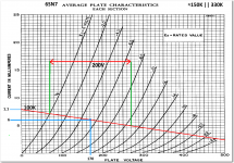
Here is my first attempt at drawing the load-line for the 6SN7 using a IXCP10M90S at 6mA with a theoretical Rdyn of 150K in parallel with 330K Rg.
The tangent to the curve at the operating point gives Ra≈10K.
The effective output impedance of FET-based current sources usually increases when they are programmed for currents lower than Idss, so if it's 150K at high current, that will will likely be as low as it gets.
OTOH, if you try out the amp with cheap 300Bs you cannot afford to exceed the max value for grid- leak resistance [250K]. I would not go above 180K personally.
A 300B that runs away with anode current can destroy an OT.
OTOH, if you try out the amp with cheap 300Bs you cannot afford to exceed the max value for grid- leak resistance [250K]. I would not go above 180K personally.
A 300B that runs away with anode current can destroy an OT.
Running cheap 300Bs above 360V is risky, too, and IME they do not sound good when overstressed. Many vesions cannot run zero anode current, regardless of bias voltage, if the anode-cathode voltage is 400V.
But at 360V 60mA they can sound good, with a bit of luck.
They sound terrible, I tried them but remember I just want to see what happens at high Va-k. I'll bring the amp up slowly on a Variac.
Also, I have just found a pre-distribution preliminary data sheet for the IXC series which gives a table for dynamic resistance. However, I'm unsure of how to interpret it. LINK
OTOH, if you try out the amp with cheap 300Bs you cannot afford to exceed the max value for grid- leak resistance [250K]. I would not go above 180K personally.
A 300B that runs away with anode current can destroy an OT.
Now that has given me an interesting idea. If I use another IXCP10M90S CSS, this time in the cathode circuit of the 300B and set it to, let's say 72mA, would this allow the use of a much larger than maximum specified grid leak resistor, given that the CSS will hold the tube current steady (within reason)? This surely should prevent catastrophic current runaway.
I do not know why the 6SN7 has taken so much criticism.
Nobody said a 6SN7 always had to be operated at 5 mA.
I had the chance to hear an extremely good sounding stereo system with Spica 50 speakers. Each mono block amp had 1250V B+, a 10k SE output transformer, and a Western Electric 212E DHT triode with filaments heated by DC.
And . . . surprise . . . a single triode of the ‘lowly’ 6SN7 driver tube was RC coupled to the 212E.
This was a ‘simple’ circuit, the 1250V supplied the 6SN7 100k plate load resistor, and the 1500V max voltage spec of the 6SN7 allowed that (lots of voltage until the 6SN7 warmed up). The coupling cap was good for 2kV.
This amp required extreme attention to details to prevent arcing, parts shorting, burn-out, etc. These were not ordinary parts, nor were they inexpensive.
I also do not know why a 300B has to use a bias of -85V to sound good; or is -85V bias required so we can use the 300B to near its maximum output power, or consider it to be a waste?
Was that a reason given for why a 6SN7 could not drive 170V peak to peak to a 300B?
I believe the 6SN7 to be a ‘tool’. Use it to its best advantage, and it can really perform.
I like to think that “all generalizations have exceptions”
I am just sayin’
Last edited:
I do not know why the 6SN7 has taken so much criticism.
Nobody said a 6SN7 always had to be operated at 5 mA.
I had the chance to hear an extremely good sounding stereo system with Spica 50 speakers. Each mono block amp had 1250V B+, a 10k SE output transformer, and a Western Electric 212E DHT triode with filaments heated by DC.
And . . . surprise . . . a single triode of the ‘lowly’ 6SN7 driver tube was RC coupled to the 212E.
This was a ‘simple’ circuit, the 1250V supplied the 6SN7 100k plate load resistor, and the 1500V max voltage spec of the 6SN7 allowed that (lots of voltage until the 6SN7 warmed up). The coupling cap was good for 2kV.
This amp required extreme attention to details to prevent arcing, parts shorting, burn-out, etc. These were not ordinary parts, nor were they inexpensive.
I also do not know why a 300B has to use a bias of -85V to sound good; or is -85V bias required so we can use the 300B to near its maximum output power, or consider it to be a waste?
Was that a reason given for why a 6SN7 could not drive 170V peak to peak to a 300B.
I believe the 6SN7 to be a ‘tool’. Use it to its best advantage, and it can really perform.
I like to think that “all generalizations have exceptions”
I am just sayin’
I think the 6SN7 is a fine tube. I'm sticking with it. BTW, do you have any opinion on the last post I did? Also take a look at the load line graph I posted earlier. With a total load of 100K, the 6SN7 can provide 200V P-P with about 340V HT using a IXCP10M90S and be quite linear.
Last edited:
According to the 300B spec, using a self bias resistor for a 300B, allows the use a fairly high resistance at the grid (RC coupling). The self bias resistor needs to have a bypass cap across the self bias resistor.
According to the 300B spec, using fixed bias for a 300B only allows the use of a fairly low resistance at the grid.
If you use a current source to provide bias for a 300B, then if the tube starts to run away (because of too large of a grid resistor), then the bias voltage will increase. A bypass cap is required across the current source. If the voltage starts to rise, the voltage rating of the bypass cap has to be larger than the voltage rating of the bypass cap for a self bias resistor. This configuration is generally not recommended.
According to the 300B spec, using a self bias resistor for a 300B, allows the use a fairly high resistance at the grid (RC coupling). The self bias resistor needs to have a bypass cap across the self bias resistor.
According to the 300B spec, using fixed bias for a 300B only allows the use of a fairly low resistance at the grid.
If you use a current source to provide bias for a 300B, then if the tube starts to run away (because of too large of a grid resistor), then the bias voltage will increase. A bypass cap is required across the current source. If the voltage starts to rise, the voltage rating of the bypass cap has to be larger than the voltage rating of the bypass cap for a self bias resistor. This configuration is generally not recommended.
it's sure worth a try though. My bypass cap is twice the voltage drop, so no problem there. The point I was making was that the tube can't possibly run away - or can it eventually?
I may have to take a look at the issue of a 6SN7, IXYS current source, and only a 340V HT.
A lot of that depends on two things:
1. The minimum voltage across the IXYS current source, when the 6SN7 passes less current, plate voltage rises, and the current from the IXYS is passed on to the R in the RC coupling.
2. The amount of negative bias voltage on the 300B. The 6SN7 and IXYS current source need to swing tow times the bias voltage (Rod Coleman was correct about the concept, the issue is how far do we need to swing with the 300B bias that we pick for the quiescent operating point).
As you develop your 300B amp, all of these things have to come together properly,
B+, bias, 300B current, output transformer primary impedance, etc.
That may be somewhat different than your original schematic.
I may have to take a look at the issue of a 6SN7, IXYS current source, and only a 340V HT.
A lot of that depends on two things:
1. The minimum voltage across the IXYS current source, when the 6SN7 passes less current, plate voltage rises, and the current from the IXYS is passed on to the R in the RC coupling.
2. The amount of negative bias voltage on the 300B. The 6SN7 and IXYS current source need to swing tow times the bias voltage (Rod Coleman was correct about the concept, the issue is how far do we need to swing with the 300B bias that we pick for the quiescent operating point).
As you develop your 300B amp, all of these things have to come together properly,
B+, bias, 300B current, output transformer primary impedance, etc.
That may be somewhat different than your original schematic.
Yes, but I've changed it 5 times already. There's going to be a long hard winter here on the West coast of Ireland, so lots of time to experiment. I have tried 5 different transformer ratios with the amp. Anything between 2.5K and 4K gives very little difference in max power output.
Last edited:
- Home
- Amplifiers
- Tubes / Valves
- Problem using Hammond 126C IST