Unless there is in-built preamplifier/source LF roll-off, then a step waveform (electronic music or stylus touch-down or switching inputs), or LF signal as per tone-arm or tape flutter or platter rumble or CD with electronic duff-duff or C-0 pipe could see a gain peaked response.
It's a subject far too seldom addressed, although in the modern era THX has helped (well, some anyway - hasn't hurt!). Antique sources need to be dealt with individually and peculiarly, but need to be dealt with. CDs made from antique sources are a moving target, of course.
Conventional valve amplifiers have a special case situation, an element with a frequency response that varies with signal level, an iron-cored inductor., the output transformer.
The overall system's response is more important from a listeners perspective, but the amplifier's internal needs are more desperate in order to achieve that.
All good fortune,
Chris
Description & One Fix for Rumble
This from Wikipedia describes a rumble fix based on the principle that the 45-45 common recording scheme utilizes both horizontal & vertical sensing.")
https://en.wikipedia.org/wiki/Rumble_(noise)
Others use both passive & active filters, there is an active Twin-T filter somewhere in Audio Anthology.
This from Wikipedia describes a rumble fix based on the principle that the 45-45 common recording scheme utilizes both horizontal & vertical sensing.
https://en.wikipedia.org/wiki/Rumble_(noise)
Others use both passive & active filters, there is an active Twin-T filter somewhere in Audio Anthology.
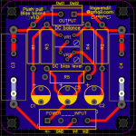
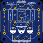
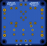
Well, I did a little more design work on the bias boards I wanted to incorporate into this build, as well as future projects. Finished them up
I sent a PM to Pete Millett asking for opinions/advice, and on his recommendation tied the end of C1 and C2 to ground rather than V- in order to prevent the coupling of ripple from V- into the grid. I also got his blessing to distribute boards, should anyone be interested in some without having to make their own. Once I have them in hand and tested I'll post up the design files for anyone that would like them.
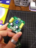
I just ordered some from JLCPCB (I had just recently sold some surplus military gear, and had a little money in my PayPal account to spend guilt free) so should have them within a week. They'll be green, as that was the fastest option and the color is unimportant.
I sent a PM to Pete Millett asking for opinions/advice, and on his recommendation tied the end of C1 and C2 to ground rather than V- in order to prevent the coupling of ripple from V- into the grid. I also got his blessing to distribute boards, should anyone be interested in some without having to make their own. Once I have them in hand and tested I'll post up the design files for anyone that would like them.
I just ordered some from JLCPCB (I had just recently sold some surplus military gear, and had a little money in my PayPal account to spend guilt free) so should have them within a week. They'll be green, as that was the fastest option and the color is unimportant.
Attachments
Alternative Parts Mounting
Those boards look very nice. But looks like I lost track somewhere, where are caps C1 & C2 in the schematic? I've looked thru the thread & couldn't them.
I never graduated to building pcb's, I was running hard selling the products of the great companies I worked for.
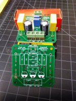
When I got back to building something the projects were all 'one of' & could not warrant the time needed to design & construct circuit boards. But there are other ways to simplify a build.
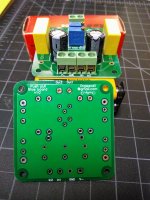
The example is the complete rectifier module I used in the clone of Norman Crowhurst's Twin Coupled Amplifier. There are 8 diodes & 12 resistors on this assembly, all on two terminal strips. So both plus & minus HV complete with equalizing & limiting resistors ready to mount in the chassis & hookup.
Those boards look very nice. But looks like I lost track somewhere, where are caps C1 & C2 in the schematic? I've looked thru the thread & couldn't them.
I never graduated to building pcb's, I was running hard selling the products of the great companies I worked for.
When I got back to building something the projects were all 'one of' & could not warrant the time needed to design & construct circuit boards. But there are other ways to simplify a build.
The example is the complete rectifier module I used in the clone of Norman Crowhurst's Twin Coupled Amplifier. There are 8 diodes & 12 resistors on this assembly, all on two terminal strips. So both plus & minus HV complete with equalizing & limiting resistors ready to mount in the chassis & hookup.
Attachments
I'm using my own parts names to make the board easier to follow as a standalone PCB, C1 and C2 are the caps from the bias voltage setpoint to ground, basically C11 and C12 from Millett's Engineer amp schematic here-
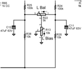
R24 and R25 on his schematic go to the output tube grids and are my R1 and R2
R24 and R25 on his schematic go to the output tube grids and are my R1 and R2
Last edited:
If you wanted to update the pcb at sometime then some 'pointy end' hi-fi suggestions would be:
- the bias supply ground would be connecting to output stage 0V node, so you could have a separate input 0V from bias supply rectifier circuitry, and a separate output 0V that goes to output stage 0V node, to minimise coupling of those two current loops.
- the balance of the signal input would preferably have the signal input pins on each end of the connector.
- the signal path via C3, C4 is being shunted to ground unnecessarily by trace and cap proximity to ground plane. Typically C3 and C4 are kept well away from chassis and other parts in a Williamson to minimise parasitic capacitance.
- C1 and C2 polarity could be swapped to reduce trace length to R1, R2.
OK, got that. But did you build Pete Millets Amp or simply use his biasing network? Guess I still thought you were building a Williamson Clone.
Simply using his biasing network here, and designed the PCB for it and future projects
It's not a real Williamson, more of a Williamson derived/inspired build, since I'm going fixed bias and a differential splitter front end.
If you wanted to update the pcb at sometime then some 'pointy end' hi-fi suggestions would be:
- the bias supply ground would be connecting to output stage 0V node, so you could have a separate input 0V from bias supply rectifier circuitry, and a separate output 0V that goes to output stage 0V node, to minimise coupling of those two current loops.
- the balance of the signal input would preferably have the signal input pins on each end of the connector.
- the signal path via C3, C4 is being shunted to ground unnecessarily by trace and cap proximity to ground plane. Typically C3 and C4 are kept well away from chassis and other parts in a Williamson to minimise parasitic capacitance.
- C1 and C2 polarity could be swapped to reduce trace length to R1, R2.
Good suggestions. I'll be making another version of the PCB with both channels on one board that will probably be tweaked a bit more. I needed mono for these monoblocks. I'm also considering doing a version with a pair of nine pine tube sockets on board as LTP splitters with CCS tails, it would make quick builds quite easy for smaller amplifier builds, like with EL84, 6V6, pentode connected sweep tubes, etc.
I'll put some "keep away" areas on the ground plane around around the pins and traces on C3/C4 for the next revision, to prevent any parasitic from being a concern. I'll switch the pinout of the screw terminals to put ground between the two inputs too.
I plan to star ground the board and each tube socket to minimise current loops in the amplifier. All the PSU stuff will be on PCBs as well so it'll be fairly easy.
Next time I'll post final pics a couple days before ordering them, but oh well. They should still do well for many projects
Last edited:
- Status
- This old topic is closed. If you want to reopen this topic, contact a moderator using the "Report Post" button.
- Home
- Amplifiers
- Tubes / Valves
- opinions on williamsonish build?