Reminds me of the Dodge ‘Plum Crazy’ color
used on the Challengers
Me also. I had/have two muscle cars, 65 &87 Mustangs.
But kept to a very conservative dark blue, bright colors attract the law.

The 87 is a Cobra vers, "T" roof & stick. Sitting in the barn now,
its winter here.
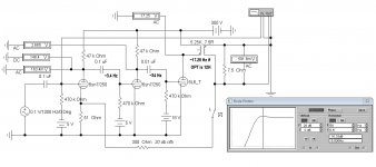
Time Constants Example in three Stage NFB Amplifier
The results speak for themselves. If two TCs are the same or close then there could be a phase reversal & NFB becomes +ve.
If the output stage was pentode there is a good chance of oscillation.
The results speak for themselves. If two TCs are the same or close then there could be a phase reversal & NFB becomes +ve.
If the output stage was pentode there is a good chance of oscillation.
Attachments
LF response gain peak/resonance/stability will be primarily dependant on the OPT inductance and output stage plate resistance. The OPT inductance will depend on the signal voltage level and any dc imbalance in the output stage. Williamson pushed that peak frequency below the coupling TC's by his transformer design and use of triode output stage, and added some phase compensation via the input stage power supply RC TC's. If you don't know your iron's performance, then setting other TC's can be hit-and-miss. You can also use a step filter on the coupling caps to play further with total phase and gain margins at LF - that was a common technique used by GEC and Partridge back then.
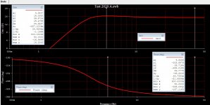
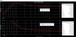
Comparison of Response with a 100H OPT
Better OPT of higher primary inductance doesn't solve the phase shift problem on its own. All other things being equal, staggered TCs help a lot.
Cathode bias TCs complicate the problem even further as do the PS TC's.
Some kind of simulator & a scope help a lot. As does experience.
Better OPT of higher primary inductance doesn't solve the phase shift problem on its own. All other things being equal, staggered TCs help a lot.
Cathode bias TCs complicate the problem even further as do the PS TC's.
Some kind of simulator & a scope help a lot. As does experience.
Attachments
All the TC's and resulting margins are preferably known upfront, otherwise the output stage/OPT resonance may be located on a coupling TC, which is a worse situation than having two coupling TCs at the same frequency and the OPT resonance way lower (or higher).
So far the OP has identified the OPT as a 'no-name output transformer' and hasn't measured the primary inductance, and appears to want to use class AB.
In a Williamson circuit with 807's in pentode mode, and a Partridge WWBF OPT, the resonance was about 4-5Hz at 3W output, which is a noticeably higher frequency than if triode mode was being used, and so the resonance has more overlap with the original Williamson coupling cap TCs.
I don't currently have a way to measure inductance, unfortunately.
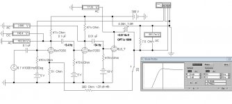
Back to your earlier comment regarding RC step networks, do you mean something like this modification from the plate to plate on the output stage? I've attached the article to help with context.
I'm open to the idea of local feedback loops also, but with the low plate resistance of the drivers I'm thinking plate to plate may be a no-go. Might be a better option with dubious iron...
I'm fully willing to admit that I'm in uncharted territory here, so any examples or recommended reading is heartily accepted my experience with feedback compensation is admittedly rather low, as I generally don't do multiple stages like this. I'm not married to having to copy a classic circuit exactly, so I'm open to different feedback compensation and solutions. I've already replaced the front end with a LTP anyways.
On the subject of grid RC time constant, I found four 1uF I can use at the grid for the outputs to get the constant even lower than the earlier coupling stages. Should the lowest frequency cutoff be at the outputs or between the LTPs?
Back to your earlier comment regarding RC step networks, do you mean something like this modification from the plate to plate on the output stage? I've attached the article to help with context.
I'm open to the idea of local feedback loops also, but with the low plate resistance of the drivers I'm thinking plate to plate may be a no-go. Might be a better option with dubious iron...
I'm fully willing to admit that I'm in uncharted territory here, so any examples or recommended reading is heartily accepted
my experience with feedback compensation is admittedly rather low, as I generally don't do multiple stages like this. I'm not married to having to copy a classic circuit exactly, so I'm open to different feedback compensation and solutions. I've already replaced the front end with a LTP anyways.On the subject of grid RC time constant, I found four 1uF I can use at the grid for the outputs to get the constant even lower than the earlier coupling stages. Should the lowest frequency cutoff be at the outputs or between the LTPs?
Attachments
Last edited:
Some info in section 8(c) on step networks in:
https://dalmura.com.au/static/Williamson%20design%20info.pdf
What meters do you have? An AVO Model 7 was used back in the 1940's to indicate primary inductance - although it would have shown a barely observable reading of AC current with a 5VAC supply.
https://dalmura.com.au/static/Williamson%20design%20info.pdf
What meters do you have? An AVO Model 7 was used back in the 1940's to indicate primary inductance - although it would have shown a barely observable reading of AC current with a 5VAC supply.
Hmmm. The more I look into it the less I'm sure of this output iron, and think I want to rely on local feedback loops a bit more. Also, to decrease the complexity of this build a bit it would be nice to reduce the extra parts.
Digging around I started to think that a pentode gain stage sounded like a great idea, and would allow for higher impedance for plate to plate feedback at the output tubes, taking less of the performance of the transformer into account. An amplifier design that I hold in high regard is Pete's Engineer's Amplifier, so I naturally looked there for inspiration. I do not have the types of signal pentode he lists as suitable (and don't plan to buy any more components for this build if I can help it) but I was recently given six of the Russian 6F12P to try out by Kodabmx. These have high gm, high mu, and very nice curves. So, I think that I could use this to make a nice pentode LTP, with the leftover triodes direct coupled to the 12AV5GA grids to help prevent blocking distortion. Since I'm using fixed bias already this is an easy enough addition. I'll plan for global negative feedback, but if it doesn't work out I'll run it with just plate to plate.
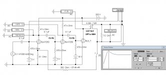
So, a rough draft of the new idea-
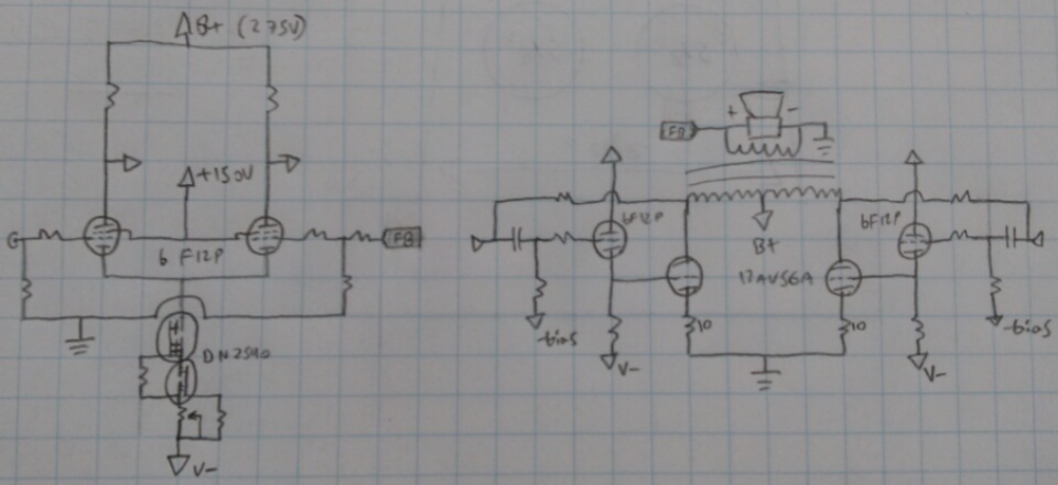
I'm thinking this is a better solution for several reasons. Primarily, less RC time constants in the signal path, less components, and all the gain in one stage rather than cascaded. It will also be my first time using pentode gain stages in a personal build of mine. One less CCS to build per channel as well. I could build all of the small signal and bias circuitry on a small PCB, and hang it between the two input sockets, which will be nice and tidy.
Any thoughts? I think this is a genuinely better overall plan.
Digging around I started to think that a pentode gain stage sounded like a great idea, and would allow for higher impedance for plate to plate feedback at the output tubes, taking less of the performance of the transformer into account. An amplifier design that I hold in high regard is Pete's Engineer's Amplifier, so I naturally looked there for inspiration. I do not have the types of signal pentode he lists as suitable (and don't plan to buy any more components for this build if I can help it) but I was recently given six of the Russian 6F12P to try out by Kodabmx. These have high gm, high mu, and very nice curves. So, I think that I could use this to make a nice pentode LTP, with the leftover triodes direct coupled to the 12AV5GA grids to help prevent blocking distortion. Since I'm using fixed bias already this is an easy enough addition. I'll plan for global negative feedback, but if it doesn't work out I'll run it with just plate to plate.
So, a rough draft of the new idea-
I'm thinking this is a better solution for several reasons. Primarily, less RC time constants in the signal path, less components, and all the gain in one stage rather than cascaded. It will also be my first time using pentode gain stages in a personal build of mine. One less CCS to build per channel as well. I could build all of the small signal and bias circuitry on a small PCB, and hang it between the two input sockets, which will be nice and tidy.
Any thoughts? I think this is a genuinely better overall plan.
Attachments
We don't need an OPT with a passband of DC to green light to build an audio amp with more than passable performance. Most of us can't hear much outside of 20 Hz to 15 KHz. And only quality speakers in a suitable space can reproduce the entire program material. I my opinion, Ling's original plan to build a Williamsonish amp makes a lot of sense. But keep it simple.
With a bit of care the lumps & bumps in the response curve should not be a problem, Altho the OPT may have questionable spec's, it seems others have used them with some success. Just need to take care that the TCs in the voltage amp part of the circuit are staggered. That is a common practice & well covered in many texts. For those folks with a copy of RDH4, check it out.
Another consideration that needs to be covered is how to drive the output tubes so that they are not overdriven at the frequency extremes. That means limiting the LF rolloff in particular.
More on some of this later today when I get out from other 'must' does here.
Either way I don't have it all ready to build just yet, need to finish mounting the PSU boards and build up bias boards, so no hurry.
Maybe I'll wire up a channel tonight quick-and-dirty just to see how it looks? If I go pentode LTP a stack of three 1N5262 zeners should be plenty for a screen supply with a series resistor. I could add another mosfet to stabilize it but I'm not sure if thats necessary. It would, however, be a handy way to go pentode connected outputs later on should I so desire
Darn, I still need to put together a negative rail. I'm thinking of just capacitor coupling a bridge rectifier and stacking it under the existing supply, unless I want to add another transformer inside each amp, but I'm not sure I have two suitable pieces on hand...
Last edited:
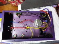
Good job on the chassis there! I've never seen a purple tube amp before, but this is sure to be a winner considering the creativity you've shown in the past. The collaborative nature of this project just adds even more inspiration.
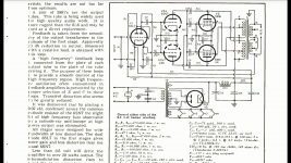
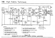
I've been watching this thread from the beginning with intense interest. Twenty years ago a good friend gave me a copy of the Radio Handbook 15th Edition he'd rescued from a dumpster. I enjoyed the ham-related stuff, but what really caught my fascination was the PP 807 Williamson audio amp in the "High Fidelity Techniques" section. I've put it off for a long time now, primarily because of laziness, but also because I'm a bit squeamish about the screen capability of the 807 in this circuit. But we'll see.
I can't wait to see how this turns out.
Attachments
Last edited:
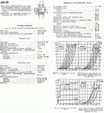
The staggering factor of the TCs in the Williamson Clone in that last post is 5, a good place to be. Also UL, so the gain is higher & the output impedance without NFB also higher. So with UL a bit trickier to hold down.
But there were quite a few very good OPTs built for UL operation at that time. And expensive. $$$ The cap on the NFB resister is specific to the OPT used.
But there were quite a few very good OPTs built for UL operation at that time. And expensive. $$$ The cap on the NFB resister is specific to the OPT used.
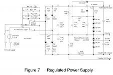
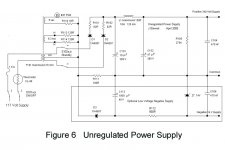
Two Easy Ways to Form a Negative Rail
Figure 7 is obvious, simply connect the SS diodes to form the -ve rail. I usually limited that to -150V so not to damage the H-K insulation of the diff amp it is connected to. In that case it was simply a resister tail of whatever current I needed. The limit of 150V set by an 0A2, VR150 or stack of Zeners.
Figure 6 gets its -ve rail from the -ve going pulses caused by the current in the main supply across the resister 100 ohm R111. Enough voltage for SS tails to attach to diff amps. Something to think about.
Never used HEXFREDS, never had noise! Keep it simple!
Darn, I still need to put together a negative rail. I'm thinking of just capacitor coupling a bridge rectifier and stacking it under the existing supply, unless I want to add another transformer inside each amp, but I'm not sure I have two suitable pieces on hand...
Figure 7 is obvious, simply connect the SS diodes to form the -ve rail. I usually limited that to -150V so not to damage the H-K insulation of the diff amp it is connected to. In that case it was simply a resister tail of whatever current I needed. The limit of 150V set by an 0A2, VR150 or stack of Zeners.
Figure 6 gets its -ve rail from the -ve going pulses caused by the current in the main supply across the resister 100 ohm R111. Enough voltage for SS tails to attach to diff amps. Something to think about.
Never used HEXFREDS, never had noise! Keep it simple!
Attachments
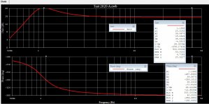
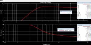
Example of Large TCs
Here is a trace test based on the comments of Kodabmx a while ago. TCs producing 1.3 Hz & 1.69 Hz are used. The cct gets into real LF territory. The ~0.5 Hz bump is smoothed out quite a bit by staggering factor of five in the 2nd trial.
But there is a problem, driving the power tube at say 10 Hz will cause excessive plate current. The reactance of the OPT primary is only 1256 ohms at 10 Hz, that in parallel with the reflected 5250 ohms of the load. If the OPT is still working as a transformer at that frequency.
So the load line is an ellipse tipped in a clockwise direction. Better to limit the drive a low frequencies. Also causes lots of intermodulation distortion on the program material.
Overdoing some things creates problems elsewhere in the cct,
Attachments

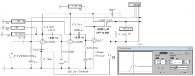
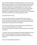
Figure 7 is obvious, simply connect the SS diodes to form the -ve rail. I usually limited that to -150V so not to damage the H-K insulation of the diff amp it is connected to. In that case it was simply a resister tail of whatever current I needed. The limit of 150V set by an 0A2, VR150 or stack of Zeners.
Figure 6 gets its -ve rail from the -ve going pulses caused by the current in the main supply across the resister 100 ohm R111. Enough voltage for SS tails to attach to diff amps. Something to think about.
Never used HEXFREDS, never had noise! Keep it simple!
I dug out the other two filament transformers that I had, rectified they give ~140 volts when run backwards off of the filament transformer, works for me. I would have run bipolar supplies from the main transformer but I'm running a full bridge off of the 277 volt winding to make up for losses running this industrial transformer backwards (I'm feeding the 120 volt secondary) if I used the 0, 240, and 480 volt lines off of it I would get only 235 volts or so rectified, which isn't really enough. I'm a simpleton so simple 1N4007 diodes here (I have a pile of them) and a CRC should be plenty to feed the bias network and negative end of the CCS(s) with ~80 volts or so.
Here is a trace test based on the comments of Kodabmx a while ago. TCs producing 1.3 Hz & 1.69 Hz are used. The cct gets into real LF territory. The ~0.5 Hz bump is smoothed out quite a bit by staggering factor of five in the 2nd trial.
But there is a problem, driving the power tube at say 10 Hz will cause excessive plate current. The reactance of the OPT primary is only 1256 ohms at 10 Hz, that in parallel with the reflected 5250 ohms of the load. If the OPT is still working as a transformer at that frequency.
So the load line is an ellipse tipped in a clockwise direction. Better to limit the drive a low frequencies. Also causes lots of intermodulation distortion on the program material.
Overdoing some things creates problems elsewhere in the cct,
This is a low power amplifier, so I think limiting the low end has great merit. There's not much likelihood of any sub ~30hz content making it through any fullrange I'm likely to run this amp with anyway
Not much more likely to happen tonight, so I'll mount the second bias transformer in the morning, and get started on the bias network PCBs, hopefully I can dig out some suitable ten-turn pots
Attachments
> 10 Hz will cause excessive plate current.
Do you have a recording with sustained 10Hz?
Rumble maybe??
> 10 Hz will cause excessive plate current.
Do you have a recording with sustained 10Hz?
Instabilities should be reduced as much as possible, just as a matter of best practices. Plenty of loudspeakers have poor diaphragm control below resonance, and some folks still play vinyl records with their fundamental (arm effective mass x cantilever compliance) resonance at ideally 10Hz.
But overall, a well designed system has a well understood and well controlled fundamental resonance.
All good fortune,
Chris
- Status
- This old topic is closed. If you want to reopen this topic, contact a moderator using the "Report Post" button.
- Home
- Amplifiers
- Tubes / Valves
- opinions on williamsonish build?