I've baked cosmoline out of firearms in the oven before, she's surprisingly understanding of my hobbies ")
Yeah the cans I have say 24 hours, which I followed. It sanded sort of funny so maybe the cans were too old. I bought them early in the year. Contrasting that I have cans of rustoleum that I've been using for small parts the same way for years without issue, maybe the formula on the colormaxx is just finicky? It doesn't seem to spray as nicely either, although in its defense you can lay on several thick coats pretty quickly without runs.
Yeah the cans I have say 24 hours, which I followed. It sanded sort of funny so maybe the cans were too old. I bought them early in the year. Contrasting that I have cans of rustoleum that I've been using for small parts the same way for years without issue, maybe the formula on the colormaxx is just finicky? It doesn't seem to spray as nicely either, although in its defense you can lay on several thick coats pretty quickly without runs.
My experience says even if there's several thick coats without runs, it'll take a kings age to cure if you don't bake it. Best to do many thin coats. Or get it professionally powder coated... Last I check in the GTA it was almost as cheap as the spray cans and it surely looks better
I'll let it cure a few days and then bake it. Final assembly won't be until next weekend at the earliest (I'm replacing the water pump in our new/used car so that's most of next weekend most likely) or later.
Next time I'll do the engine enamel with ceramic from the auto parts store. It's easy to use and tough, just a little pricy and limited in color selection. That or hammertone like the last few chassis builds.
Next time I'll do the engine enamel with ceramic from the auto parts store. It's easy to use and tough, just a little pricy and limited in color selection. That or hammertone like the last few chassis builds.
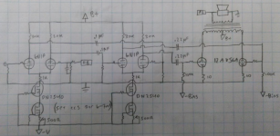
Preliminary copy of the more-or-less final schematic, power supply and bias supply not shown, but will be about ~270 volts most likely. Pardon the messy drawing style 12AV5GA drawn pretty simple, but you get the idea. Output transformer is 6k:8 (3K:4) plate to plate. Some TBD parts values aren't yet labeled, of course, as more testing and parts-on-hand adjustments will be made. Yes, I know the CCS is drawn wrong
I figure that using the DN2540 cascode CCS would work well here, and I have a handful of them in my stock. I'll use the TO92 package on the bottom, and the TO220 up top, as the bottom devices have just a few volts across them. I'll be able to vary the tail current for 6-7mA to start, and this should give me about ~165-170 volts across each triode, with ~11k or so plate resistance. my 30K plate resistors should be just adequate here without undue distortion, as it's pretty close to the 2.5-3x Rp recommendation usually seen. I could go for higher current at the supply voltage I have to work with and drop down to a 24-27K resistor even, but the curves still look good at these currents so I don't know if it's necessary. Besides, my supply voltage is definitely a limiting factor here, so if I were to increase the current too much I would need higher voltage to accommodate a larger load resistor, so it's a tradeoff I can't really make here. I understand that the DN2540 isn't the best for applications of less than 10mA, so I'm open to the basic NPN bipolar cascodes as well, I just don't have any that sport higher voltage capabilities on hand. I'll be doing some more reading on possible improvements or alternatives today.
Current plan is a CCS under each differential, unless there is a compelling reason to go without on the second set. If I went that way in order to keep gain high I would need to use bypassed cathodes, which I'd rather just use the CCS to eliminate.
Anybody want to sim the effect of my 30K plate resistors, versus 22k, 24k, and with CCS tail current ranging from 6, 7, 8, 10mA? I don't have access to a PC that I can run sims on. I'm curious to how this cascade of differentials will work.
12AV5GA drawn pretty simple, but you get the idea. Output transformer is 6k:8 (3K:4) plate to plate. Some TBD parts values aren't yet labeled, of course, as more testing and parts-on-hand adjustments will be made. Yes, I know the CCS is drawn wrong I figure that using the DN2540 cascode CCS would work well here, and I have a handful of them in my stock. I'll use the TO92 package on the bottom, and the TO220 up top, as the bottom devices have just a few volts across them. I'll be able to vary the tail current for 6-7mA to start, and this should give me about ~165-170 volts across each triode, with ~11k or so plate resistance. my 30K plate resistors should be just adequate here without undue distortion, as it's pretty close to the 2.5-3x Rp recommendation usually seen. I could go for higher current at the supply voltage I have to work with and drop down to a 24-27K resistor even, but the curves still look good at these currents so I don't know if it's necessary. Besides, my supply voltage is definitely a limiting factor here, so if I were to increase the current too much I would need higher voltage to accommodate a larger load resistor, so it's a tradeoff I can't really make here. I understand that the DN2540 isn't the best for applications of less than 10mA, so I'm open to the basic NPN bipolar cascodes as well, I just don't have any that sport higher voltage capabilities on hand. I'll be doing some more reading on possible improvements or alternatives today.
Current plan is a CCS under each differential, unless there is a compelling reason to go without on the second set. If I went that way in order to keep gain high I would need to use bypassed cathodes, which I'd rather just use the CCS to eliminate.
Anybody want to sim the effect of my 30K plate resistors, versus 22k, 24k, and with CCS tail current ranging from 6, 7, 8, 10mA? I don't have access to a PC that I can run sims on. I'm curious to how this cascade of differentials will work.
Attachments
Last edited:
Be sure the RC time constants of the coupling between the 1st & 2nd stage are somewhat different than the RC time constants (TCs) of the 2nd to 3rd stage. Otherwise a phase shift approaching 180 degrees will occur & LF stability with NFB is compromised. Watch also for that to occur sometimes with the OPT TC to load. Triode output stage helps a lot. Sometimes there are problems with TCs in the PS as well.
Williamson's are none to exhibit 'heavy LF breathing' under some conditions. Watch the loudspeaker diaphragm move slowly in & out.
Williamson's are none to exhibit 'heavy LF breathing' under some conditions. Watch the loudspeaker diaphragm move slowly in & out.
Well, with 220nF/100k I'm at 7.2hz for the outputs, but on the differential coupling I haven't set a value yet for the grid resistors. Would 680k/100nF for 2.3hz, or 510k/100nF for 3.1hz be a good bet, or am I still too close? I could up the size on those coupling caps but that would mean I need to source more, I only have four 220nF caps on hand that would be suitable, but maybe a dozen or so 100nF on hand that would work. Could just parallel them if needed, or maybe hunt down some 1uF from dead projects
I plan to get the amp nice and complete before trying GNFB, but want to make sure it's set up for success as much as I can first. Would it be wise to place an RC network between the plates of the driver plates at the first stage to rolloff HF? I see this is done from plate to ground on classic Williamson implementations, but I'm in unfamiliar territory with a differential up front.
I plan to get the amp nice and complete before trying GNFB, but want to make sure it's set up for success as much as I can first. Would it be wise to place an RC network between the plates of the driver plates at the first stage to rolloff HF? I see this is done from plate to ground on classic Williamson implementations, but I'm in unfamiliar territory with a differential up front.
My "go to" is 1.59Hz 1.3Hz, and 1.7Hz. I want my amp to be flat from 20Hz up, not -3db so that makes me use TCs under 2Hz. So far they play nicely, although I've seen the LF "breathing" jhstewart was talking about when I was using Hammond iron and I solved it with batter RC filtering for the VA stage.. With the Triads, that isn't a problem. Indeed they will make my woofers dance at 5 Hz generated in audacity
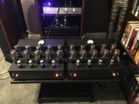
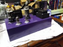
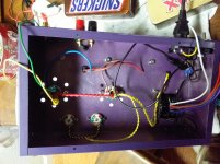
Couldn't resist, started final mechanical assembly. I'm really digging the hammertone with the purple
Reminds me of the Dodge ‘Plum Crazy’ color
used on the Challengers
Couldn't resist, started final mechanical assembly. I'm really digging the hammertone with the purple
Reminds me of the Dodge ‘Plum Crazy’ color
used on the Challengers
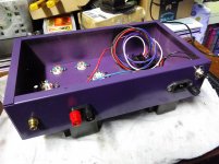
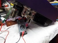
Got the AC and heater wiring done on one block last night, and also discovered my usual meter is reading erratic and off a bit. Grabbed another couple meters and found that my filament transformer gives 12.5 volts with all tubes in place, much better than the ~14 shaky volts that the other meter was giving. I also found that the power transformer gives 330 rectified without load, dropping to 295 with a 100mA load. Much better than the ~280 that I initially thought I was getting. Still need to figure out a bias supply piggybacking arrangement. The filament transformer is warm, and the power transformer is barely above ambient
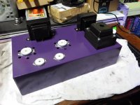
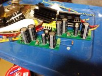
I really like the little Mosfet PSU PCBs I made, makes the power supply tedium much quicker
Yellow twisted pair is the leads from the filament transformer, I'll tuck it out of the way better later on. Don't mind the clip leads you see running all about, I had a couple things going on at once.
I really like the little Mosfet PSU PCBs I made, makes the power supply tedium much quicker
Yellow twisted pair is the leads from the filament transformer, I'll tuck it out of the way better later on. Don't mind the clip leads you see running all about, I had a couple things going on at once.
Attachments
Last edited:
- Status
- This old topic is closed. If you want to reopen this topic, contact a moderator using the "Report Post" button.
- Home
- Amplifiers
- Tubes / Valves
- opinions on williamsonish build?