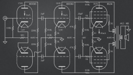
I would like to build a new amplifier, this time with classic tubes references.
I wonder if I have drawn the see saw / paraphase inverter correctly?
Maybe a little bit of gNFB will be needed, in this case is it better to remove local feedback between ECC82 and EL34?
I didn't find max value of Rg1 for EL34 in fixed bias mode, 80-100K is fine?
OPT is 4.2K / 8 ohms with 2 & 4 ohms too (Quicksilver), maybe I'll use 4 ohms tap with 8 ohms speakers for better damping and easier life of EL34's. 20W is more than enough for my use.
Do you see errors on this schematic?
Thank you.
Attachments
Each stage should be decoupled from each other. You have them tied together at the same 400V point. Good if you like motor-boating...
Thanks, you're right, I'll add a LC then RC for the first stage.
As it is, it probably has too much gain for today's sources. EL34s don't need that much voltage drive.
Local feedback can work great. However, plate to plate LFB is usually done with pentode (high impedance) driver stages. With low impedance triode stages it is less effective.
Also, the ECC82 has a bad rep here for it's less than stellar linearity. In PP with some feedback it can work well, but you can consider other types.
I am not stuck with ECC82, the idea was to use usual noval double triode types as I have many of them.
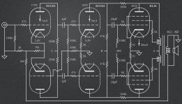
Yes, probably too much gain even if cathodes not bypassed, a good idea to add a little bit of gNFB like this?
Another (better?) option could be to connect the driver as a cathode follower.
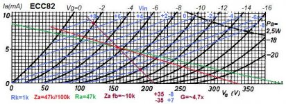
Interesting graph Ketje. Could you tell me if the calculated gain of 4.7x is with unbypassed cathode resistor?
Do you see this as a possible issue or not really?
Thank you both.
Yes, probably too much gain even if cathodes not bypassed, a good idea to add a little bit of gNFB like this?
Another (better?) option could be to connect the driver as a cathode follower.
Interesting graph Ketje. Could you tell me if the calculated gain of 4.7x is with unbypassed cathode resistor?
An unbalance of ~15% pos- versus neg- drive, but cansels (more or less) in the output stage.
Do you see this as a possible issue or not really?
Thank you both.
Attachments
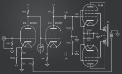
But then no more feedback in the power stage.Unless a series resistor at the output of the follower and that gives the need of a to large voltage from the ECC83 for comfort.Another (better?) option could be to connect the driver as a cathode follower.
The blue lines are what you get with the 1k cathode resistor, bypassed gives the original black curves.Interesting graph Ketje. Could you tell me if the calculated gain of 4.7x is with unbypassed cathode resistor?
Do you see this as a possible issue or not really?
How much of the distortion get through depends on how well balanced the output stage is and how well matched the two halfs of the ECC82.
Mona
- Status
- This old topic is closed. If you want to reopen this topic, contact a moderator using the "Report Post" button.
- Home
- Amplifiers
- Tubes / Valves
- EL34 project