Hi guys, I was trying to find a spec sheet for the new version of the Tung-sol 7591s. I've heard they are a hotter tube than the originals. The only spec sheet I can find was on tubedepot and its the one for the original tube from 1961. Cheers
Unfortunately, the one Steve linked is from 1961 also.
The Tung-Sol website has the datasheet, but they've just replaced the bottom line of the sheet with an overlay saying New Sensor. It's the old datasheet, too.
Tung-Sol.com:: 7581 Vacuum Tube page
If it is a true 7591 that spec will do. If figures are different it is no 7591Hi guys, I was trying to find a spec sheet for the new version of the Tung-sol 7591s. I've heard they are a hotter tube than the originals. The only spec sheet I can find was on tubedepot and its the one for the original tube from 1961. Cheers
Ok now I'm really confused. This is listed as a 7581 not a 7591, and why doesn't ts when list a 7591. Or more specifically a 7591A is what they are being Marketed as.Unfortunately, the one Steve linked is from 1961 also.
The Tung-Sol website has the datasheet, but they've just replaced the bottom line of the sheet with an overlay saying New Sensor. It's the old datasheet, too.
Tung-Sol.com:: 7581 Vacuum Tube page
*edit* just noticed that the tube they call a 7581 has a different pinout than the 7591.
Last edited:
If it is a true 7591 that spec will do. If figures are different it is no 7591
I don't get why multiple resellers of the tube, including Jim Mcshane are telling me I'll b need to rebias the amp and the dissipations are different on the new tube when all written specs are the same. WTH is going on? On paper it looks like it is a drop in replacement.
Last edited:
Tube characteristics will vary +-20% or more, and they did so even in the good old days. Thats why you have to rebias.I don't get why multiple resellers of the tube, including Jim Mcshane are telling me I'll b need to rebias the amp and the dissipation temps are different on the new tube when all written specs are the same. WTH is going on? On paper it looks like it is a drop in replacement.
Thanks for the insight but I think there's more to it than that. Here is a snippet from McShanes website. "Important note - updated! There have been some cases where the new production 7591A (and 7868) tubes have had troubleTube characteristics will vary +-20% or more, and they did so even in the good old days. Thats why you have to rebias.
in circuits using a very high value grid resistor - as vintage Scotts, Fishers, and others sometimes do. The best solution is changing
all the grid resistors to 200K-220K from the original value, since often the factory spec resistors exceeded the maximum
recommendations. For instance, Fisher routinely used 330K carbon resistors that would often drift up to 360K over time! As well,
to prevent loss of deep bass energy a change of the output coupling cap value to .1 uf (preferred) is needed. I stock all the parts
you need, the parts cost is only $15.00 to $30.00 per amp, depending on the coupling cap you prefer to use. As well, many amps
will require adjustable bias to be installed to accommmodate the available tubes. "
And here is what he said in an email to me."
I believe your amp has adjustable bias – if it doesn’t it would need to be installed. Also, the stock amp has no means to measure the bias. The easiest solution is to install 10 Ohm 1 watt resistors in each tube cathode from the cathode to ground. This will allow you to read the voltage across the resistor and use Ohm’s Law to calculate the current flow. You want no higher than 35 ma. of cathode current through any single tube – otherwise they will exceed the maximum dissipation level they can handle.
And here is what Warren Coleman said from ValueTubes "
I would count on rebiasing the amp. The new 7591s, both EH and TS, run a bit hotter than the older Sylvanias for example. To avoid having to rebias, you will want to stick to NOS or good tested used. I only have a matched quad of GE coin base 7591 available but I do see quite a few others selling good used 7591s on eBay now."
It doesn't sound to me like its spec'd the same as the old ones. All I want to see is the new dissipation values so that I can properly bias the amp.
Last edited:
It's no surprise that newly made tubes has different characteristics then old used ones.
you should always ( this is not new) check/adjust bias in fixed bias amps when changing power tubes. Even new tubes from the same brand will vary a lot, that's why using
matched tubes are important for best balance and lowest distortion.
you should always ( this is not new) check/adjust bias in fixed bias amps when changing power tubes. Even new tubes from the same brand will vary a lot, that's why using
matched tubes are important for best balance and lowest distortion.
Go to Gillespie's site.
He has an extensive tests of NOS v repro 7591 with Q & A
All your questions will be answered.
Bearing in mind a 7591 is HALF a 8417 stuffed in a 6V6 glass, and you will get why it's impossible to replicate exactly.
The problem with high gain valves like this, they self bias, and propel themselves rapidly towards melt down if not spot on.
The repro ones are made in eastern Europe, who never made /tried to make them originally.
As far as I am aware it's a Westinghouse design like the 8417 was.
Last edited:
Awesome! Thanks for the info. That is exactly the kind of resource I was looking for. CheersGo to Gillespie's site.
He has an extensive tests of NOS v repro 7591 with Q & A
All your questions will be answered.
Bearing in mind a 7591 is HALF a 8417 stuffed in a 6V6 glass, and you will get why it's impossible to replicate exactly.
The problem with high gain valves like this, they self bias, and propel themselves rapidly towards melt down if not spot on.
The repro ones are made in eastern Europe, who never made /tried to make them originally.
As far as I am aware it's a Westinghouse design like the 8417 was.
The 7591 was state-of-the-art for mass-production in 1961, and even then not all US factories could make it consistently well. Grid location and treatment is very critical.
I gave-away a 7591 amp when the old stock dried up.
There's big demand, so asian factories are making a thing "like" a 7591. Since some old 7591 amps really pushed the limits of the best original 7591, the new-made tubes may not work in old holes without changes. Not just bias but too-bold grid resistances. With all this, some of the HIGH-gain advantage of 7591 is given-up. However 1961 is never going to come back, so we do what we can.
That was a bit silly.The 7591 was state-of-the-art for mass-production in 1961, and even then not all US factories could make it consistently well.
Grid location and treatment is very critical.
I gave-away a 7591 amp when the old stock dried up.
I have loads of NOS, which are an exact equivalent by Sylvania.
Only thing is they don't have the same pin out of the originals (hint), and are actually better with a bigger cathode.
There is also a small British made valve, which when fitted in pairs actually outperforms the 7591 and is more linear.
One does have to say, they were a little economical with the truth in that ad.
You won't exceed 43W with the 7591(A) at the onset of clipping.
They upgraded the original 7591, because it couldn't meet spec.
With all the US amplifiers made at the time, it's well known with both channels driven almost without exception they couldn't exceed 22-25per ch, without gross distortion...so yes in an odd way it became "45 watts" from both channels driven at 1.5%THD,- also impossible if run ultralinear.
I have to say I'm a great admirer of the "ancient"* octal base 7591, because it was so much better than anything before, but was sadly never exported to Europe.
In effect, in a half size more economical package it left the 1930s 6V6 behind.
It absolutely WHOPS the 1950s Mullard Octal EL34 & the 6GM5, the smaller noval EL84.
I say "ancient"*, because Philips pushed the Novar/Magnoval format with valves like the EL503/EL520 3-4yrs later, and the octal was dead by 1965.
Those had TWICE the gain in an even smaller package, able to hit 100W from a pair with as little as 350V HT, but they hardly sold.
We all know what happened,- Magnoval died, the 7591 was squashed down into an even smaller Novar 7868, then the Noval 6GM5 which we also never saw in Europe.
I would like to hear a comparison between a British amp fitted with EL84, then fit it with 6GM5.
I know which I would prefer!
By the time those amps were 3-4yrs old the transistor had arrived, so I never saw one.I will build up a PPP amp with several, using Bogen 83-366-000 or 83-371-000 output transformers as soon as I get time this winter.
American TVs got giant size valves,like the 6LF6 which are absolute treasures.
We in Europe had to make do with more Mullard Noval junk, as the US went to superb 12 pin creations.
(Philips branded their fragile noval stuff as hi tech and "advanced").
I don't think so.
Nobody in China is making this.
I think it's the ultimate irony making the new 7591 repro in Eastern Europe.
You won't exceed 43W with the 7591(A) at the onset of clipping.
They upgraded the original 7591, because it couldn't meet spec.
With all the US amplifiers made at the time, it's well known with both channels driven almost without exception they couldn't exceed 22-25per ch, without gross distortion...so yes in an odd way it became "45 watts" from both channels driven at 1.5%THD,- also impossible if run ultralinear.
I have to say I'm a great admirer of the "ancient"* octal base 7591, because it was so much better than anything before, but was sadly never exported to Europe.
In effect, in a half size more economical package it left the 1930s 6V6 behind.
It absolutely WHOPS the 1950s Mullard Octal EL34 & the 6GM5, the smaller noval EL84.
I say "ancient"*, because Philips pushed the Novar/Magnoval format with valves like the EL503/EL520 3-4yrs later, and the octal was dead by 1965.
Those had TWICE the gain in an even smaller package, able to hit 100W from a pair with as little as 350V HT, but they hardly sold.
We all know what happened,- Magnoval died, the 7591 was squashed down into an even smaller Novar 7868, then the Noval 6GM5 which we also never saw in Europe.
I would like to hear a comparison between a British amp fitted with EL84, then fit it with 6GM5.
I know which I would prefer!
By the time those amps were 3-4yrs old the transistor had arrived, so I never saw one.I will build up a PPP amp with several, using Bogen 83-366-000 or 83-371-000 output transformers as soon as I get time this winter.
American TVs got giant size valves,like the 6LF6 which are absolute treasures.
We in Europe had to make do with more Mullard Noval junk, as the US went to superb 12 pin creations.
(Philips branded their fragile noval stuff as hi tech and "advanced").
There's big demand, so asian factories are making a thing "like" a 7591.
I don't think so.
Nobody in China is making this.
I think it's the ultimate irony making the new 7591 repro in Eastern Europe.
Last edited:
Thanks for the insight but I think there's more to it than that. Here is a snippet from McShanes website. "Important note - updated! There have been some cases where the new production 7591A (and 7868) tubes have had trouble
in circuits using a very high value grid resistor - as vintage Scotts, Fishers, and others sometimes do. The best solution is changing
all the grid resistors to 200K-220K from the original value, since often the factory spec resistors exceeded the maximum
recommendations. For instance, Fisher routinely used 330K carbon resistors that would often drift up to 360K over time! As well,
to prevent loss of deep bass energy a change of the output coupling cap value to .1 uf (preferred) is needed. I stock all the parts
you need, the parts cost is only $15.00 to $30.00 per amp, depending on the coupling cap you prefer to use. As well, many amps
will require adjustable bias to be installed to accommodate the available tubes. "
And here is what he said in an email to me."
I believe your amp has adjustable bias – if it doesn’t it would need to be installed. Also, the stock amp has no means to measure the bias. The easiest solution is to install 10 Ohm 1 watt resistors in each tube cathode from the cathode to ground. This will allow you to read the voltage across the resistor and use Ohm’s Law to calculate the current flow. You want no higher than 35 ma. of cathode current through any single tube – otherwise they will exceed the maximum dissipation level they can handle.
And here is what Warren Coleman said from ValueTubes "
I would count on rebiasing the amp. The new 7591s, both EH and TS, run a bit hotter than the older Sylvanias for example. To avoid having to rebias, you will want to stick to NOS or good tested used. I only have a matched quad of GE coin base 7591 available but I do see quite a few others selling good used 7591s on eBay now."
It doesn't sound to me like its spec'd the same as the old ones. All I want to see is the new dissipation values so that I can properly bias the amp.
I told you how to properly bias your amp. With roughly 450 volts on the plate (the stock value is 430 volts, but that's with a 117 volt AC line voltage - today's line voltages are often 5% or so higher than that which means about 450 on the plate). and essentially zero volts on the cathode and cathode current of 35 ma. you'll have total dissipation of 15.75 watts.
The Tung-Sol current production 7591As are quite happy at that wattage or just a hair more (you could bias them at 38 ma if you want). But in my experience many of the Tung-Sols develop excess heater-cathode leakage or excessive grid current at total dissipation above 17 - 17.5 watts. So regardless of what the old spec was, I don't recommend - nor do I guarantee - the tubes be run at any higher dissipation than I just mentioned.
As well, the ratings shown by the data sheet on the New Sensor/Tung-Sol site are ratings reached using the "Design Maximum" rating system. This is a rating system that is significantly less conservative than the "Design Center" rating system that is most often used. In fact the Design Maximum ratings are 10% higher than the Design Center values.
According to the GE Essential Characteristics manual here are the definitions of the two ratings:
Design-Center Rating System: To establish conformance to the design-center rating system, the ratings should not be exceeded with a bogey tube operating in the equipment under average conditions with respect to supply voltage, signal, temperature, component values, adjustment of controls, and other variables.
Design-Maximum Rating System: To establish conformance to the design-maximum rating system, the ratings should not be exceeded with a bogey tube operating in the equipment under the worst probable combination of conditions with respect to supply voltage, signal, temperature, component values, adjustment of controls, and other variables.
You can find a complete discussion of the ratings in the TubeCad journal here:
http://www.tubecad.com/december2000/page17.html
So consider that:
a) the amp is likely running at 20 volts or so higher plate and screen voltage than it was originally
b) the published 7591A ratings are showing the less conservative Design Maximum ratings system
c) my real-world experience with testing/matching hundreds of Tung-Sols indicates that while some tubes will perform properly at the Design Maximum dissipation specs many of them will not! And looking at the schematic of the 7591 version of the S-5000 II I see it does not have adjustable bias.
d) your S-5000 II originally ran the 7591s at a cathode current of about 51 ma. per tube and with 430 volts on the plate. That yields a total dissipation of 22 watts per tube - which exceeds even the Design Maximum spec by over 15%! Back in the day the tubes could often withstand this sort of abuse - and tubes were cheap and readily available. That's not true anymore.
e) finally, the new Tung-Sols tend to bias hotter than the old stock tubes did. By hotter I mean that they have higher cathode currents (and therefore higher total dissipation) at any given set of operating conditions.
On the basis of those 5 points I recommend 35 ma. per tube as a safe bias current. And that was why I made the recommendations I did.
Thank you for that incredibly in depth explanation! I appreciate you taking that time to spell that all out for me. I didn't realize how much thought went into your recommendation and I didn't understand the theory behind it. But now I do. Cheers
Lots of people don't understand the theory of valve control grid negative potentials (called "bias"). The history is important.
Eg. some industrial triodes are designed to operate with "zero bias", ie at full anode volts and operating conditions they automatically are safe, and won't destroy themselves. They operate on the basis of driving the grid strongly positive.
When you drive a control grid positive it behaves a litttle like a diode between the grid and cathode, so has a low impedance and requires current to drive it, but operates in a region where the anode impedance also has a lower value it will drive more current through a load.
This is why transmitting valves commonly use these traits.
6V6 and 807 (an upgraded 6L6) both are originally transmitting valves, while the British KT66 with its higher ratings emerged from the ruins of a failed transmitting valve production line.
To get safe operation under these conditions with the tooling/tolerances of the 1930s, the internal spacing of the grids were conservative, the screen grid (g2) was aligned with the control grid (g1), and the internal gain remained quite low.
In addition to the problems of alignment the screen was relatively prone to heat and distort so a maximum value of 300V was adopted.
This limited output.
Valves with low internal gain adapt badly to modern implementations of negative feedback through the screen grid, (ultralinear connections using taps on the output transformer) quite simply because of the lack of gain.
This explains why the older valves (correctly as Williamson reasoned) were no good for ultralinear connections, so he originally recommended using the KT66 straight as a triode.
Even order distortions produced by push-pull amplifiers cancel out in the output transformer.
They leave the less harmonious odd order distortion, but the older valves struggled to make enough power, and used as a beam tetrode often produced high levels of distortion when driven hard out of its idle zone (where it is effectively producting least distortion in class A).
If you look carefully you will see 3 difficult & diverging trends.
1/ The need to get higher and higher powers because of less efficient speakers with better fidelity.
Requiring extensive operation outside class A.
2/ The need to make things more and more compact,- when stereo appeared in the 1950s, amplifiers originally had to double in size, because before then they were all monoblocs.
3/ The need to reduce distortion for the higher powers, at the same time as not reducing valve life, by increasing the gain of the output valves, requiring more precise assembly, and more rigid structures which wouldn't distort over time.
The USA and Europe basically parted ways over this last question.
The Soviets continuing to make the older 6L6 based designs (because they were sold this technology during the war by the Americans). It appears to me the Chinese got their industry from the Russians..
The British dominated by the Dutch giants Mullard, and GEC-Marconi a major military supplier went their own way.
So, Mullard threw their weight behind Pentodes like the EL34 and EL84 (which the Americans only saw in their own beam tetrode version 6CA7), GEC threw their weight behind the "KT series" KT66, KT77, and KT88, and their outstanding TT21/TT22 industrial series.
The best gains of these valves were often double those of the old 6L6, and could stand much higher voltages. Along came "rock" pushing for much higher power and lower rig weights.
Maximum power from a pair of valves shot up from about 20-30W to more than 70 in most cases.
Used in multiple pairs and we were talking in 100s.
The US answer were Westinghouse's fantastic 7591 and 8417, sold to their main manufacturers, Scott, Eico, Bogen, Dynaco, and especially FISHER, then along came colour TV, and things went a quantum leap further in just 5 years. That doesn't concern us here.
In the bias game there is an obvious golden rule.
The higher the valve's internal gain, the less drive it requires. This revolves around smaller clearances inside the valve, but makes it more fragile if something distorts or gets damaged.
This gain termed "transconductance" is quantified in ma/V m/a for the current it will conduct and V being the drive (put simply). in Mhos the standard measure, the old 1930s valves usually measuring about 4500-6000.. the 1960s valves were roughly double, typically around 9000-11000.
The peak of 1960s technology was the introduction of frame type grids with much tigher tolerances resulting in gains of double again where the 8417 hit a value of 23000mhos.
This was made specially for Fisher, who interestingly rightly didn't believe in ultra linear for such high gain components.
As a result, another divergence appeared between the purists, and the UL people.
Some of the amplifiers made from this period have never been bettered, but the technology to make the valves successfully disappeared with the arrival of the yet again 20x more compact transistor, then the microchip.
So, to come back to Bias, raise the screen grid voltage, raise the gain, and you get a valve with high power, low distortion and can be run successfully ultralinear, which people equate with those sweet 60s sounds, and the ability to drive modern speakers 50 yrs later.
Bias requirements are directly related to SCREEN voltage,because the screen sets the internal gain of the valve, not essentially Anode voltage, so Mcshane is wrong here.
The 7591 being in the centre of this technology nexus was the "sweet spot", a valve with the size of a 6V6, but half the distortion, and 3x the power output.
The penality for all this extra gain, is insane amounts of screen grid current, but so long as the thing doesn't melt, all is fine.
The European EL34 Pentode is an obvious case. Pentodes fundamentally cannot align grids.
Drive it real hard with say a square wave test for maximum power and it will DIE.
Beam power valves got around this problem via another route, but make higher IMD as a result.
High IMD like say in earlier Dynacos can be quite objectionable.
As such these later audio valves depend on just one thing to survive.
The relationship between peak to average power is wide enough to prevent the screen melting.
Typically you could get away with a bias of -21v at 450v anode, 400v screen.
If you drop the screen voltage you can get away with near 30% less bias, at -16.5v bias at 350V screen (see how it matters?).
The ouput drops by a mere 2W.
That would be my favoured technique to handle the question in this thread.
So:-
If you compare the bias requirement of a typical high power amp of the 1940s, it needed -28.5V bias at 500V, and 100V of output valve drive.
When Bogen dropped 4 off, 7591 into their little 60s Challengers (they used 7868), they could get reliably near 100W from just 20v of bias and only 40V of drive.
To get the thing so compact they economised on the power supply, like many US makers did, and ran much closer to the lean Class B, which because of cross over distortion sounds quite bad.
Scott's main weakness was the inadequate power supply, but in typical conditions nobody would notice back in 1965.
50 years later it's a different story with speakers requiring lots more power.
Fact is,- if the modern 7591 repro requires more bias to have lower idle current, the gain is lower.
I can't think of any other maker that ran quads of them in the 60s apart from Bogen.
If it's running high dissipation at idle, it means it may stay longer in the Class A region, so will "sound sweet" like the original, which is what people are hearing, and measures well.
Run a matched quad of them, can't really be bettered, but people don't.
This would mean the internal structure has not exactly the close, difficult to make tolerances of the original Westinghouse design.
Fact is, you have now reached the limits of the 60s compacting process.
You can drop the idle current by lowering the screen voltage, because this drops the internal gain.
You can INCREASE the bias voltage to say -22/-23v, but obviously this requires higher drive voltage to get the same power.
It all goes to show you never get a free lunch.
Last edited:
"Bias requirements are directly related to SCREEN voltage,because the screen sets the internal gain of the valve, not essentially Anode voltage, so Mcshane is wrong here."
No sir - you are incorrect. I never wrote about gain at all. I only wrote about dissipation which is calculated by the formula:
Total dissipation = (Plate voltage - cathode voltage) x cathode current
I wanted to ensure the Sherwood's owner could set the bias current in such a way that the Tung-Sols could operate properly and not be required to dissipate too much wattage (with the issues that would cause).
"Bias requirements are directly related to SCREEN voltage,because the screen sets the internal gain of the valve, not essentially Anode voltage, so Mcshane is wrong here."
No sir - you are incorrect. I never wrote about gain at all. I only wrote about dissipation which is calculated by the formula:
Total dissipation = (Plate voltage - cathode voltage) x cathode current
Sorry but this is incorrect.
Do you not agree with me in a pentode there are as its name suggests 5 electrodes?
Cathode
grid 1 known as control grid.
grid 2 known as screen grid
grid 3 or beam plates - supressor grid
Anode.
The anode to cathode potential is the exact equivalent of a DIODE.
That is exactly what a rectifier has in it, so it cannot flow the opposite way.
You have just stated that is how your pentode operates is this:-
(Plate voltage - cathode voltage) x cathode current, which is plainly wrong, because it is not a diode and there are other more important things in there....
If you add grid 1 to a diode you get a TRIODE, so it conducts current in direct proportion to the negatively charged grid, which STOPS current flowing to its logical maximum as would a diode without the grid.
The amount of change of current in this Triode is directly affected by its GAIN.
More negative bias is required to shut down a low gain valve than a high gain valve.
When you add a SCREEN grid, g2, this acts as an ANODE because it attracts electrons from the cathode, after they have gone past grid 1.
Therefore the screen grid is the most important electrode in a pentode/beam tetrode.
Don't tell me it's the anode.
It's not, the anode is a "virtual electrode in the shadow of the screen grid and supressor.
The supressor is there to try to stop high speed electrons bouncing off & being knocked back into the valve stream.
If you don't believe me, see what happens when you disconnect the screen.
Current will not flow.
Try instead to disconnect the anode, leaving the screen grid connected and you will see it glow white hot and melt in front of your eyes.
Strap the screen grid to the anode and it will conduct no problem and behave then as a Triode instead.
If you want to measure the total dissipation of the valve it is neccessary to measure the Anode AND Screen grid current.
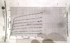
It does state very clearly on the 7591 documentation that the screen grid under high loads can dissipate as much as 6W.
That's 1/3 of the anode...in fact it states the current can be as high as 30m/a.
At idle it's 5-8m/a
I am pretty sure the reason why the repro 7591 differs from the OEM one is because of a difference in the placement of the screen grid.
Right brief theory lesson over.
FACT, if you want to reduce the current flow through a pentode you can decrease the screen grid voltage.
This is very effective and makes the valve run considerably cooler.
I stated the bias requirements are directly related to the GAIN of the valve.
The 8417, the highest gain mass produced pentode made, only requires 15V of negative bias to work perfectly cool at over 600V.
The 7591 needs -21V to work correctly at a lot lower 450V, precisely because it has HALF the gain of the 8417.
The 6L6 needs even more bias, because it half the gain of the 7591, typically -25V or more at 450V.
So you see the direct relationship between bias and gain.
If a repro valve needs more bias to set its idle current it has LOWER gain, because obviously at the normal given voltage for the OEM part, the repro valve will be off the scale and even red plating the anode.
You can increase the gain by increasing the screen grid voltage, - that will just increase the cathode current, or alternatively reduce the gain further by reducing screen voltage.
That of course brings the valve back under control.
Here is exactly the page that proves it.
All valves come with graphs, which is exactly what they are for.
Here is the one you need to see.
Attachments
- Status
- This old topic is closed. If you want to reopen this topic, contact a moderator using the "Report Post" button.
- Home
- Amplifiers
- Tubes / Valves
- Does anyone have specs for the "new" Tung-sol 7591s