I've had my eye on building the Pete Millett 6B4G / 6S4S (6C4C in cyrillic) / or possibly 6A3 (with adapter) amp (version 2) for over a year now, its truly an "old school" amp as you can see... I'm close to actually getting started on it. I just keep coming back to this lovely schematic after bouncing around looking at hundreds of others. Maybe that's how hobbyists with this unhealthy addiction operate, look at thousands of schemes and wait for that one to continually haunt you saying "build me" please.
But I do want to make one customization of my own... I want to make the on/off switch be a double throw with center off on/off/on so you can turn on the amp with either AC heaters or DC heaters. Not as a fallback if I fail to make the AC hum free, but to struggle making the AC work just as hum free as the DC, but have the option of either.
I was going to buy the Rod Coleman current regulator to power the DHT power tubes with DC.
But If the user chose to power up the amp in the "DC heaters" switch position, I also have those 6SL7 and 6SN7 tubes there. Assuming I'm not exceeding the current, can the Coleman regulator do all the tubes for me? Or do I have to acquire a second DC filament source to do the indirect tubes separately? IOW can I mix indirect and DHT tubes on a Coleman regulator? I may do two Coleman regulators, one for each channel so they run cooler. I will be separating the PS from the stereo amp with umbilical and aircraft connectors rated for high voltage which I already have.
http://www.pmillett.com/file_downloads/6B4_V2.PDF
If you were thinking of using the single 6.3 V winding on the power transformer to double up for either AC or DC operation via a suitable switching mechanism this will not work.
You'll loose some volts making DC from AC so if you want to go down the DC route you will need a higher voltage AC windings. Also each Coleman DHT regulator needs its own transformer winding or very preferably its own transformer.
How many Coleman DHT regulators? Ideally one each for each 6B4G. Although you could run a single one in parallel with possibly unpredictable results. But why economise on DH regulators (if indeed there is a saving as the power transformer will need to be even beefier).
You could keep the 6SL7 and 6SN7 tubes on the parallel 6.3 VAC line and they would not benefit from being DHT regulator powered. Not that you would need to do so as you would break the DHT tubes out of the circuit leaving the two IDH tubes on AC.
Why not build the amp as per schematic and if you want to go down the DC route try that as a phase 2. Make sure you leave enough growing room in your PS chassis though for the DC transformers.
Hello,
Like you can read in the previous post using one regulator for each 6B4G.
Read the info on Rod Colemans website and you will know how to do it. If you have any questions he will answer you very quickly.
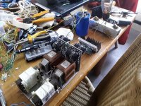
See my Vt25A 7,5 V 1,25 A supply. i used triad split bobbin and a choke input with lundahl LL2733. greetings, eduard
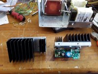
P.s as you can see they need a decent cooling.
Like you can read in the previous post using one regulator for each 6B4G.
Read the info on Rod Colemans website and you will know how to do it. If you have any questions he will answer you very quickly.
See my Vt25A 7,5 V 1,25 A supply. i used triad split bobbin and a choke input with lundahl LL2733. greetings, eduard
P.s as you can see they need a decent cooling.
Attachments
Push-pull DHTs can be heated with the filaments in parallel, but if you do it the best way (high-impedance current-drive) each should have its own regulator, to prevent the signal (anode-current and end-to-end voltage) from cross-talking.
How does a signal voltage appear across the Filament?
- The 6B4G filament is 6.3V 'nearer' to the grid at the +ve end of the filament, due to the filament voltage - So the grid voltage (Vg→k) is 6.3V hotter at the +ve end.
This means the gm is different (higher) at the +ve end - and this effect produces a differential voltage across the filament, representing the signal (the music).
This best solution, as suggested, is AC for the indirectly heated voltage-gain stages, and purpose-designed regulation for the directly-heated 6B4G.
If you were thinking of using the single 6.3 V winding on the power transformer to double up for either AC or DC operation via a suitable switching mechanism this will not work.
You'll loose some volts making DC from AC so if you want to go down the DC route you will need a higher voltage AC windings. Also each Coleman DHT regulator needs its own transformer winding or very preferably its own transformer.
How many Coleman DHT regulators? Ideally one each for each 6B4G. Although you could run a single one in parallel with possibly unpredictable results. But why economise on DH regulators (if indeed there is a saving as the power transformer will need to be even beefier).
You could keep the 6SL7 and 6SN7 tubes on the parallel 6.3 VAC line and they would not benefit from being DHT regulator powered. Not that you would need to do so as you would break the DHT tubes out of the circuit leaving the two IDH tubes on AC.
Why not build the amp as per schematic and if you want to go down the DC route try that as a phase 2. Make sure you leave enough growing room in your PS chassis though for the DC transformers.
I understand, and I didn't struggle with how to do the on/off/on switching yet at all, it's just all wish list stuff for now. if I have to use totally separate filament transformers so be it, the PS chassis will have to be roomy. The thordeson transformer isn't made anymore, Hammond has a suitable substitute, but what I may do instead is go with a dedicated HT transformer and two filament transformers and chokes, this will allow me to use a toroid for HT and smaller high amp EL core filament X formers. Without the height of a tall HT transformer I can make the ps be a "brick" all enclosed with only a well protected 5u4 on it to sit on the floor even. Maybe with a quiet 50mm fan and vents. This would be the ideal form factor for me on the PS making it be as close to being a brick as possible. The chassis I will make by hand from sheet stock, because I love doing fabrication with metal work just as much. And I want to play with aesthetics make it a enjoyable process.
I understand, and I didn't struggle with how to do the on/off/on switching yet at all, it's just all wish list stuff for now. if I have to use totally separate filament transformers so be it, the PS chassis will have to be roomy. The thordeson transformer isn't made anymore, Hammond has a suitable substitute, but what I may do instead is go with a dedicated HT transformer and two filament transformers and chokes, this will allow me to use a toroid for HT and smaller high amp EL core filament X formers. Without the height of a tall HT transformer I can make the ps be a "brick" all enclosed with only a well protected 5u4 on it to sit on the floor even. Maybe with a quiet 50mm fan and vents. This would be the ideal form factor for me on the PS making it be as close to being a brick as possible. The chassis I will make by hand from sheet stock, because I love doing fabrication with metal work just as much. And I want to play with aesthetics make it a enjoyable process.
The planning is part of the fun. Enjoy.
Just regarding the amount of real-estate needed for your PP DHT PSU's.
You're probably looking at 4 filament transformers - split bobbin EI types one each for each tube (2 left + 2 right for stereo). Rod has all the info you need to help you design and specific the TX's you'll need. Probably stock Hammond iron will be available.
Then you need to make the raw DC boards, again another 4. IMO you could usefully go down the CRC raw DC boards route rather than CLC. Rod has some excellent CRC boards and these are economic / excellent / take up modest space.
You could probably cool that lot with convection alone, but a quiet fan is a nice touch.
The metal work - you've got that covered!
For connectors / umbilicals Amphenol mill-spec or XLR will probably be all you need.
Sounds like a lot? Well yes, but well worth it (IMO).
Have fun!
Hello,
Like you can read in the previous post using one regulator for each 6B4G.
Read the info on Rod Colemans website and you will know how to do it. If you have any questions he will answer you very quickly.
See my Vt25A 7,5 V 1,25 A supply. i used triad split bobbin and a choke input with lundahl LL2733. greetings, eduard
P.s as you can see they need a decent cooling.
Nice craftsmanship eduard! Is that a solid chunk of aluminum spreading the heat below the black heatsinks?
For what I'm thinking of doing heatsink-wise... do you think the TO220 devices can be connected to the board with a short 2 inch umbilical instead of being a soldered part on the board itself? If this is ok to do, this will give me more flexibility on positioning the heatsink on the chassis because it would not have to physically carry the whole board too. Freeing the TO220 device from the board makes heatsinking through a chassis top pretty easy because parts are separated. I was thinking of using CREE round LED heatsinks because they look cool on a chassis top, I sand, polish and anodize these myself. Using caustic soda, RIT clothing dye, and a car battery charger and acid.
I have a whole bunch of these left over from some lighting I made for my basement remodel. But I'd need to umbilical the regulators over to the boards to mount them properly. It avoids machining a rectangular hole in my chassis too which is always helpful. I used one of these on a headphone amp I made for my son and they look cool after you sand them and anodize them:

5pcs 3.5x0.8inch Round Spiral Aluminum Alloy HeatSink for 1-10W LED Silver White | eBay
The planning is part of the fun. Enjoy.
Just regarding the amount of real-estate needed for your PP DHT PSU's.
You're probably looking at 4 filament transformers - split bobbin EI types one each for each tube (2 left + 2 right for stereo). Rod has all the info you need to help you design and specific the TX's you'll need. Probably stock Hammond iron will be available.
Then you need to make the raw DC boards, again another 4. IMO you could usefully go down the CRC raw DC boards route rather than CLC. Rod has some excellent CRC boards and these are economic / excellent / take up modest space.
You could probably cool that lot with convection alone, but a quiet fan is a nice touch.
The metal work - you've got that covered!
For connectors / umbilicals Amphenol mill-spec or XLR will probably be all you need.
Sounds like a lot? Well yes, but well worth it (IMO).
Have fun!
Rod has been great! I have an order in for four of each board reg and dc. As for umbilicals I actually found a quality part at non-Amphenol prices in China. 25mm aircraft connectors, no ratings but with 25mm of real-estate the pins are thick and widely spaced. These arrived a few days ago and they look build worthy so far not "low-voltagy" looking at all:
10Set GX25 XLR 2 3 4 5 6 7 8 9 10 Pin 25mm Female Male Disc Flange Panel Mount Socket with Dustproof Cover Aviation Connector-in Connectors from Lights & Lighting on AliExpress
I like those connectors.
Hello,
It is indeed a solid chunk of aluminium but the temperature was on the higher side so i ordered two cheap heatsinks at mouser to lower the temperature considerably.
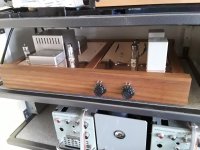
The aluminium was thrown away at work so just had to cut it to the right length, add some holes and two threaded holes to mount it on the inside of my future chassis which will look like my last line amp in the attachment.
With the way i constructed the Coleman it can be moved easily because it needs just 2 M4 holes to be attached to the top plate.
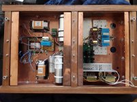
The other aluminium metal construction holds two transformers, two input chokes and the caps that will feed the two Colemans which will be mounted right under the tube.
I prefer choke input but you will need 4. Dave Slagle in the USA makes a choke input supply with the Coleman circuit too.
Greetings, eduard
It is indeed a solid chunk of aluminium but the temperature was on the higher side so i ordered two cheap heatsinks at mouser to lower the temperature considerably.
The aluminium was thrown away at work so just had to cut it to the right length, add some holes and two threaded holes to mount it on the inside of my future chassis which will look like my last line amp in the attachment.
With the way i constructed the Coleman it can be moved easily because it needs just 2 M4 holes to be attached to the top plate.
The other aluminium metal construction holds two transformers, two input chokes and the caps that will feed the two Colemans which will be mounted right under the tube.
I prefer choke input but you will need 4. Dave Slagle in the USA makes a choke input supply with the Coleman circuit too.
Greetings, eduard
Attachments

- Status
- This old topic is closed. If you want to reopen this topic, contact a moderator using the "Report Post" button.
- Home
- Amplifiers
- Tubes / Valves
- Coleman regulator ok for all the tubes in the circuit?