Hi guys, I'd like to add adjustable bias to my Sherwood S5000II. I can solder but I'm not great with electronics yet. I'm attaching a schematic. The power tubes are 7591s. Is there someone who can tell me if this has fixed or cathode biasing and where would want to install bias pots? My best guess is replacing r45 and r85 with adjustable pots but I'm really just guessing. I'm also installing 10 Ohm resistors from cathode to ground so that I can measure bias per Jim McShane's advice but I don't know how to add bias adjustment. Advice is greatly appreciated! Cheers
Attachments
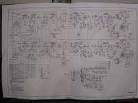
The schematic is to fuzzy to see what you mean with r45 and r85.
The amp is fixed bias, the bias comes at the "-22V" points.
You could mount 2 pots , one for each channel, from the -29V where the viper goes to the
"-22V" ( and remove the existing connection). But you better make sure that the bias supply can take the extra load from the pots.
The amp is fixed bias, the bias comes at the "-22V" points.
You could mount 2 pots , one for each channel, from the -29V where the viper goes to the
"-22V" ( and remove the existing connection). But you better make sure that the bias supply can take the extra load from the pots.
I don't know why the schematic looks blurry on the attachment. The original image on the phone looks great. I'll attach another source but the schematic is broken up where they separated the pages, and there is some overlap. I had to zip it to get it to fit under the size requirements.
Attachments
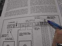
OK so I took new pics one of each page. I think these will work better. It looks like you were referring to r5, where the -22 volts are, which is actually what they call an "output tube balance control" which is a 2 part pot for left and right. You're supposed to adjust those to reduce hum. But since that is an adjustable pot does that mean there is already bias control? In the attached image I've pointed to the adjustment knob that is R5 in the schematic which is the -22v point you referred to.
Attachments
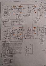
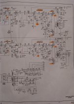
Those pots are indeed for bias adjustment, but they adjust the relative bias of the two valves in each channel. Adjusting for minimum hum is a crude way to zero the standing DC field in the output transformers. Your plan to add 10 Ohm sensing resistors is much better.
The next step beyond this would mean two more pots, each adjusting the bias voltage for its channel. An alternative would be four separate cathode bias resistors, each with a big capacitor bypass, and no pots.
All good fortune,
Chris
The next step beyond this would mean two more pots, each adjusting the bias voltage for its channel. An alternative would be four separate cathode bias resistors, each with a big capacitor bypass, and no pots.
All good fortune,
Chris
If I were you, but I'm not, I'm an old service technician, but I think Sherwood got it designed right back in their laboratory.
With that said, I'd leave well enough alone, which you probably will ignore.
I've serviced those old Sherwoods, and they didn't ever need "mods" or messing around with the bias.
Oh, and Jim McShane isn't all the "guru" that people think he is.
I've had to impliment my own "professional" brain experience when dealing with his Harman Kardon kits - he leaves out critical "changes" that are required and not mentioned with his kits.
Last edited:
Hi Wiseoldtech, I appreciate your feedback and I'm all ears. Look I'm a novice, I'm just trying to get this old amp going again. And I'd like to learn a thing or two along the way. I'm just trying to source tubes for this amp. I can't afford old stock 7591's and I was just trying to buy the reissue Tung Sols from Jim. I never said I thought he was a guru. But I can pass along his concern and see what you think.
He stated "...many amps will require adjustable bias to be installed to accommodate the available tubes. I believe your amp has adjustable bias – if it doesn’t it would need to be installed. Also, the stock amp has no means to measure the bias. The easiest solution is to install 10 Ohm 1 watt resistors in each tube cathode from the cathode to ground. This will allow you to read the voltage across the resistor and use Ohm’s Law to calculate the current flow. You want no higher than 35 ma. of cathode current through any single tube – otherwise they will exceed the maximum dissipation level they can handle."
That's all the available info I had and that's why I'm trying to figure this out. If I can avoid messing with changing the circuitry I'd like to do so, but I don't want to put the new tubes in peril because of differences in specs between new and old tubes. I'd appreciate your input. Thank you.
Is the bias voltage typically on the cathode (pin 5 on the 7591)? If so, then can I simply replace he 6.8 Ohm resistors (R45&R85 on the schematic) with the appropriate pots? Or is there more to it than that? Cheers
This biasing is called "fixed bias" although it's often adjustable - your Sherwood is truly "fixed" with the same average bias applied to all valves' G1. Judging from your response, I'd guess that drilling into your classic chassis to install more pots may not really be what you'll want to have done, down the road.
As a conservative first step, maybe you should add your 10 Ohm cathode current sensing resistors and get a true feel for the bias currents as-is. Be careful, be safe, and let us know the voltages you measure across those resistors.
All good fortune,
Chris
Hi Chris, thanks again for your response. This is probably a stupid question, but do the tubes I'm going to end up with going to change the bias current values that I derive from the 10 Ohm resistors? The amp came with only 2 functioning output tubes. I don't have the new tubes yet. Also, do I even need tubes inserted to measure bias current? If its truly fixed bias then I'm thinking hat resistance and voltage don't change so I should be able to get away with it? Cheers
Perform any restoration that is needed.
Get the amp working properly.
I have some JJ 7591 tubes that work very well.
Purchase a set of JJ 7591 matched tubes from eurotubes.com.
Enjoy listening.
Thanks for replying. I was actually trying to stay away from the JJs. I've read many online reviews of the JJ 7591s failing very early. I haven't seen those sorts of reviews for the Tung Sol's although I'm sure every manufacturer has duds.
Sorry, another note, and if this is obvious to you, please don't be offended: if you install the 10 Ohm sensing resistors, you'll also need to disconnect the existing 6R8 resistors. Everything is obvious after you already know it.
All good fortune,
Chris
Ha, no offense taken. Its not obvious to me at this point, I'm a novice. Here's a question on that line of thought. Is it possible for me to measure voltage drop on the 6.8 Ohm resistors and derive current from Ohm law from there, then divide by 2 to get an estimation of the cathode current to each tube, assuming the tubes were balanced with those balance pots we talked about earlier?
Cheers
10 Ohm resistors in the cathode circuit sense cathode current.
If there is no 7591 in the socket, there is no cathode current.
Yeah I thought it was a stupid question...

Thanks!
Is it possible for me to measure voltage drop on the 6.8 Ohm resistors and derive current from Ohm law from there, then divide by 2 to get an estimation of the cathode current to each tube, assuming the tubes were balanced with those balance pots we talked about earlier?
On the nosey. Assumptions are getting me into trouble here. How are your power supply electrolytics? How is the (probably) selenium rectifier for heaters and bias? These need to be addressed first, if that's not obvious.
All good fortune,
Chris
Over a couple of decades or more, JJ has constantly been improving all of their tubes performance and sound, and also a much improved reliability.
I have been using JJ tubes from eurotubes.com for a long time now.
They do additional testing of the tubes when they come here from Slovakia.
These are not tubes that sat on the shelf from years ago, waiting for a buyer.
Some quick ways to kill a good tube:
Put it in an amplifier that exceeds the tube rating(s).
Use coupling caps that are leaky. (I use modern 600V coupling caps in amps that have a B+ rise to 500V before the tubes warm up and draw current).
A 450V cap is no good here.
Misadjust the bias.
Try and use a Hi Fi amp to play Van Halen at max power, all the way through side one of the vinyl that has a very bad record warp at 3 Hz. The output transformer primary acts like a short.
etc.
On the nosey. Assumptions are getting me into trouble here. How are your power supply electrolytics? How is the (probably) selenium rectifier for heaters and bias? These need to be addressed first, if that's not obvious.
All good fortune,
Chris
As far as the electrolytics, the only ones in the amp are in 4 cans. They are original and I will be restuffing those. All of the coupling caps and most other caps in the entire amp are the El Menco brown drop plastic dipped mylars, so no electrolytics there. I've read some promising things about those El Mencos (not to be confused with brown turds). The consensus is that they don't degrade like electrolytics and I wasn't planning on replacing those. Do you have any first hand experience with them? There are no selenium rectifiers to deal with.
Cheers
- Status
- This old topic is closed. If you want to reopen this topic, contact a moderator using the "Report Post" button.
- Home
- Amplifiers
- Tubes / Valves
- Adding adjustable bias to S5000ii