Hi!
I've had a few of those cheap Soviet battery valves sat around for a while (1J29B and 1P24B)
I'm a relative novice in valve circuit design, but I've studied a few schematics on the www, and come up with a couple of 'first shot' ideas. Dont expect perfection, I've only ever made simple stages using 3 or 4 variety of valves, and a simple output stage.
I plan to build and test these ideas, and optimise them (provided they work at all)
My planned applications are probably instrument based effects, but whilst a harmonic generator may be useful, I also plan on making an iteration as clean as possible, so I will also be making effort to reduce THD, as well as create musical THD.
Something about DHTs seem to make circuits more difficult to design (perhaps that's all in my head)
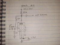
I have drawn a couple of basic designs for using 1J29B in pentode mode, B+ 60V Vg2 45V; and also a triode wired operating on 45 to 60V. For the time being these will be powered using multiple PP3 batteries.
I would be grateful if some of the more seasoned designers could look over the schematics, simple as they are, and offer some practical critique/advice.
I've had a few of those cheap Soviet battery valves sat around for a while (1J29B and 1P24B)
I'm a relative novice in valve circuit design, but I've studied a few schematics on the www, and come up with a couple of 'first shot' ideas. Dont expect perfection, I've only ever made simple stages using 3 or 4 variety of valves, and a simple output stage.
I plan to build and test these ideas, and optimise them (provided they work at all)
My planned applications are probably instrument based effects, but whilst a harmonic generator may be useful, I also plan on making an iteration as clean as possible, so I will also be making effort to reduce THD, as well as create musical THD.
Something about DHTs seem to make circuits more difficult to design (perhaps that's all in my head)
I have drawn a couple of basic designs for using 1J29B in pentode mode, B+ 60V Vg2 45V; and also a triode wired operating on 45 to 60V. For the time being these will be powered using multiple PP3 batteries.
I would be grateful if some of the more seasoned designers could look over the schematics, simple as they are, and offer some practical critique/advice.
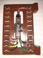
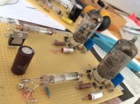
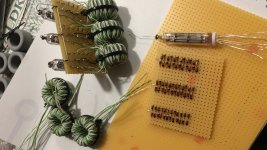
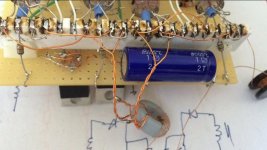
Attachments
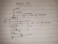
The filament battery is important for correct bias. You want the middle of the heater to be positive relative to grid to get correct negative bias. The way your filament battery is drawn look wrong to me.
I have not looked-up your tube but 22k seems an awful heavy load for a very small thin tube. You won't get a lot of signal voltage before distortion. Maybe that's "good"?
But what is your question?? You say the tubes are cheap. TRY THEM! You'll learn more in a couple sessions than forum-yack can ever tell you. Don't get the filament across a fat B battery (not a problem for the old 67V batts which would just sag, but you are probably using wall-plug supplies). Be sure there is many-K resistance in series with the plate so it can't try to suck infinite current.
")
I built a mic amp with 1j24b which is similar to 1j29b but with even lower heater power. They were happiest with 90-100 volts on the anode and a couple of milliamps. I think I biased them with several 1N4148 and a current source. The filament was powered by a D cell and a dropping resistor. They were utterly non-microphonic and the sound was very clean but I didn't keep it as the hiss was a bit high for purpose (this could possibly have been oscillation, although I did take the usual precautions). I also wondered if the hiss was a consequence of the very low heater power.
Edit: They were triode wired.
Edit: They were triode wired.
Last edited:
Hi,
Firstly,
PRR, the anode load much more than an arbitrary value that I inserted for the sake of having a number.
Maximum cathode current is 5 to 8mA at most, so 22k is the absolute minimum. More likely it would be double or more, say 47k to 100k.
The exercise of drawing a crude schematic is more to form up the idea in my head. Admittedly DH are more difficult for me to get my noggin around.
Regarding the filament, design voltage is 1.2V in parallel connection, centre tap being the earthy end. So I'll probably use a alkaline cell, with resistor to drop 0.3V.
After posting in haste, I did consider that I would probably need a cathode resistor, which I hadn't thought through (still havent...) - cathode bypass isnt something I have thought about just yet either.
The 1J24B, if I recall, is lower dissipation than 1J29B, although I'll add the remark that there is conflicting information online, incorrect links and tube codes, even on Radiomuseum.
However, these are cheap. I have 10 and they're probably about £1 each or less by the time shipping costs included.
1J29B are from what I read useful for 500mW front end AF
1P24B, the "power" tubes, are more costly but I have a few of those too! The history behind them (Sputnik) is fascinating.
They certainly arent proximity fuse types, judging by the information online, though some of this type certainly were (1J17B?)
I have also seen the headphone amp schematics using variants of these rod pentodes, and in might just build one of those in time. The biggest problem with that is my 300R Sennheiser is not the intended 600R load!
HearinSpace,
Indeed I have read Thomasha thread, viewed his videos, some months ago, and that lead me to try and find out more. It certainly helped me get a feel for what is possible if I utilise more than 1% of my brain!
His mini amp, even sounded pretty good - not amazing, but hell, I'd be chuffed to bits with it if I designed it. But it kind of drops off the edge of a cliff, as so many threads do.
So, ok...a couple of mA anode current. I can do that.
90V is pretty much datasheet max anode volts.
Diode or LED bias is definitely something I'll try with these, maybe a CRD diode at 1-2mA.
Thanks, really helpful stuff!
Last edited:
> I would probably need a cathode resistor
No. This is awkward when you do not have insulated heater-cathode tubes. These tubes are normally biased with a combination of a large (5Meg) grid resistor, and the ~~ Volt drop across the heater (grid tied to one end, +1V at the other end, the "average" grid bias is -0.5V, which with grid-R drop is often enough).
Plagiarize plagiarize plagiarize!!! Study all the beach-radio schematics you can find.
Disco, you've lost me a bit there.
Yes, heaters in || are about 100mA. (50mA each)
Dropping 0.3V from 1.5V cell, by my simple reckoning, requires 0.3/0.1 = 3R stopping resistor. 3R3
12V supply at 100mA, needs about 0.1A*11V drop, 110R resistor. Probably 120R nearest value.
Unless I am missing something (quite possible)
Yes, heaters in || are about 100mA. (50mA each)
Dropping 0.3V from 1.5V cell, by my simple reckoning, requires 0.3/0.1 = 3R stopping resistor. 3R3
12V supply at 100mA, needs about 0.1A*11V drop, 110R resistor. Probably 120R nearest value.
Unless I am missing something (quite possible)
Last edited:
Hi again Lampie,
Can you expand on your remark that these pentodes dont like to be triode wired?
A few of drawings I have seen, seems to use as pentode, and I did find one drawing using triode mode.
Oddly it seems to use G2 and G3 at anode potential, rather than G3 at cathode earth end potential.
Can you expand on your remark that these pentodes dont like to be triode wired?
A few of drawings I have seen, seems to use as pentode, and I did find one drawing using triode mode.
Oddly it seems to use G2 and G3 at anode potential, rather than G3 at cathode earth end potential.
I tried to use these pentodes as triodes by connecting G3 to the anode, but somehow then there was not enough gain (actually no gain). Maybe the voltages were incorrect for the triode mode operation in my case. I also tried using G3 as input (enhanced) but this also did not work as desired. So i just use them as intended and they work excellent this way.
Thanks, that makes some sense to me.
I thought it was unusual to tie both G2 and G3 to anode; this is why I remembered it! It was likely in one of the longer Radiomuseum threads about these things.
Now I'm no expert, or even novice, but G2 drive or Crazy drive might be an interesting experiment, being as these pentodes are functionally similar though structurally miles apart from conventional pentodes.
Sadly the Gòogleplex hasn't offered me any curves, either pentode or triode wired for the 1J29B.
the search continues
1P24B however, I do have some 3rd party curves for triode wiring.
To correct an error in my earlier post, in parallel, the filament current is about 60mA.
Thus, 0.06*(12-1.2) gives about 180R dropping resistor for 12V supply.
I've just tried that and it is spot on, at 1.18V across the filament.
I^2R comes out at 0.65W dissipation in that resistor.
From before at 100mA and using a 1.5V cell, I calculated 3R resistor, so scaling that, I think 2R2 dropper with 1.5V cell would work well. Less dissipation, less noise rejection, I guess
Last edited:
- Status
- This old topic is closed. If you want to reopen this topic, contact a moderator using the "Report Post" button.
- Home
- Amplifiers
- Tubes / Valves
- First shot at a battery DHT preamp stage