Hi,
I have a Lafayette LA224B that I am in the process of swapping out many of the carbon compound resistors. While I have it in bits I thought I would change some of the caps.
The problem is the schematic is pretty unreadable as far as values are concerned. The resistors I can tell by the colour code, but some of the caps don't give any clue.
Does anyone know if there is a component list or a readable schematic available?
Take a look here;
https://elektrotanya.com/lafayette_la224b_sch.pdf/download.html
https://elektrotanya.com/lafayette_la224b_sch.pdf/download.html
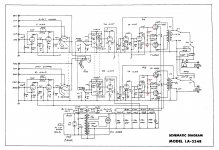
Many thanks for the reply and link. This is the schematic I already have, and as can be seen a lot of the values are blurred enough to be uncertain, plus there are no voltage values.
Attachments
Use the PC to zoom up the pdf file. You should be able to read it after knowing what the typical value are:
For example the 6BQ5 cathode by pass is 100uF. You can use 100V safely. The coupling capacitor to the 6BQ5 grid are 0.05uF. You need > than B+ for these. I would use at least 450V. The cathode by-pass cap to the 12aX7 read 25uF and 25V+ should be enough. The coupling cap to the 12AX7 preamp stage should b .1uF. You need 450V+ for these. The tune stack caps are ,005uf 100pf and .02uf. Use >B+ for these as well.
For example the 6BQ5 cathode by pass is 100uF. You can use 100V safely. The coupling capacitor to the 6BQ5 grid are 0.05uF. You need > than B+ for these. I would use at least 450V. The cathode by-pass cap to the 12aX7 read 25uF and 25V+ should be enough. The coupling cap to the 12AX7 preamp stage should b .1uF. You need 450V+ for these. The tune stack caps are ,005uf 100pf and .02uf. Use >B+ for these as well.
Use the PC to zoom up the pdf file. You should be able to read it after knowing what the typical value are:
For example the 6BQ5 cathode by pass is 100uF. You can use 100V safely. The coupling capacitor to the 6BQ5 grid are 0.05uF. You need > than B+ for these. I would use at least 450V. The cathode by-pass cap to the 12aX7 read 25uF and 25V+ should be enough. The coupling cap to the 12AX7 preamp stage should b .1uF. You need 450V+ for these. The tune stack caps are ,005uf 100pf and .02uf. Use >B+ for these as well.
Many thanks for that information. That has given me a a good idea as to what I am looking at.
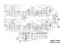
I have run into a bit of a problem. In my search for suitable components to make the replacements, I don't seem to be able to find any 250K 1/2Watt resistors. See image (values in red). I can find 270K 1/2Watt 1% metal film. would this value be okay or would it cause problems?
Attachments
I can find 270K 1/2Watt 1% metal film. would this value be okay or would it cause problems?
The 274k 1% 1/2W metal film resistor is better than stock. The larger value won't pose any problem,
since the upper limit is 1M in this application.
Last edited:
The 274k 1% 1/2W metal film resistor is better than stock. The larger value won't pose any problem,
since the upper limit is 1M in this application.
I just turned the place upside down and found 5 x 220k 0.6W 1% and 6 x 33K 0.6W 1% They were in a box of components in the loft that I had completely forgotten about.
")
I just turned the place upside down and found 5 x 220k 0.6W 1% and 6 x 33K 0.6W 1%
They were in a box of components in the loft that I had completely forgotten about.
The 220k will be fine by itself, there's no need to series it with the 33k.
Last edited:
The 220k will be fine by itself, no need to series with the 33k.
Thanks guys, I'm good to go now then.
Thanks guys, I'm good to go now then.
The tolerance on all these R and C parts was 10% or even 20%, so changing a part value
by that much remains well within spec.
Finished replacing the carbon compound resistors, while I was in there I experimented by rewiring all the five 12AX7 valve sockets to 6N2P-EV (rocket logo) matched valves.
It's just a matter of connecting pin 9 to ground (shield between the two halves) and 4 & 5 to the 6.3V heater windings.
There are two 6.3V windings, one 2.2A and one 2.5A. One feeds 2 x EL84 & 2x 6N2P-EV, the other feeds 2 x EL84 & 3 x 6N2P-EV.
They were wired in two chains from the transformer, I changed this to four chains, two for the left and right EL84 output valves, and two for the 6N2P-EV valves.
There used to be a static scratching noise and slight buzz with the volume up, these have now gone, I have no idea if this was as a result of a change of resistors, valves or heater wiring, or a combination.
The 6N2P-EV valves have slightly less gain than the 12AX7 valves, but for me not enough to matter, but the result is a much nicer sound, the whole thing sound more full and rounded, especially at the bottom end.
Now comes the strange part, the 6N2P-EV valves draw more heater current than the 12AX7 valves, though still within the scope of the transformer. Despite this, the valves themselves don't get as hot as the 12AX7 and neither does the transformer, I'm lost for a logical answer as to why.
Last edited:
One thing I have found is that the phono input/preamp for magnetic cartridges is rubbish. The turntable I have has a switchable RIAA preamp.
When I use the preamp built into the deck, plugged into the Aux inputs everything sounds okay, but if I switch that off and swap the inputs to the amplifier preamp Mag inputs it sounds as tinny as hell.
The amp has two inputs for record decks Mag & Cer. I haven't tried the ceramic input as I don't have a suitable cartridge.
The only difference between the two phono inputs is a 150pf capacitor on the ceramic input.
The preamp sounded just as bad with the 12AX7 valves in place.
Attachments
Last edited:
One thing I have found is that the phono input/preamp for magnetic cartridges is rubbish. The turntable I have has a switchable RIAA preamp.
When I use the preamp built into the deck, plugged into the Aux inputs everything sounds okay, but if I switch that off and swap the inputs to the amplifier preamp Mag inputs it sounds as tinny as hell.
The amp has two inputs for record decks Mag & Cer. I haven't tried the ceramic input as I don't have a suitable cartridge.
The only difference between the two phono inputs is a 150pf capacitor on the ceramic input.
The preamp sounded just as bad with the 12AX7 valves in place.
How did the phono input sound before all component replacements ?
How did the phono input sound before all component replacements ?
It has always been awful. Very treble, no base.
...the phono input/preamp for magnetic cartridges is rubbish...
Agree. It has problems even Lafayette could have seen, so I assume it is "value enginered" to make a higher price model sound better.
I started marking it up but it really needs all new values and more B+ to get "good". Excellent would need a 3rd stage (buffer). There's many 12AX7 plans around, add a MOSFET on the end.
However back in the day Lafayette was never considered a Great Brand, just convenient because there were Lafayettes in every town and the prices were affordable.
There was still a small amount of noise, but only with the volume right up. While testing to try and find the cause, I pulled the two preamp valves and all the noise disappeared.
I don't use the preamp section as I use the RIAA preamp built into the record deck.
Is it okay to run the amp with those two valves pulled? I checked the heater voltage with them pulled just in case the reduced load caused a voltage rise, not that it should, unless it was overloaded to begin with. The voltage was 6.3 on one chain and 6.4 on the other, so no problem there.
- Status
- This old topic is closed. If you want to reopen this topic, contact a moderator using the "Report Post" button.
- Home
- Amplifiers
- Tubes / Valves
- Lafayette LA224B recap