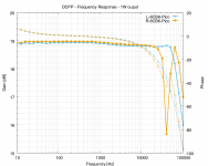
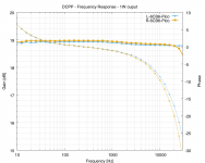
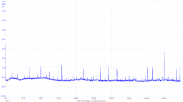
Any ideas for what would cause the wierd 'notch' in my frequency response at 40kHz (attached) for the right channel? My OCD side would prefer that both channels be closer.
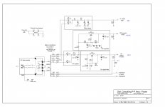
Schematic: http://pmillett.com/file_downloads/dcpp_sch.pdf
I have the 6dB NFB connected. The notch appears with differing valves in both pre and power positions. But I haven't gone to the extent of swapping OTs and seeing if the problem follows.
Should I even care? I won't hear it... (attached plot of audio frequency sweep) But am hoping it's not a sign something else is wrong.
This amp is being used for a few hours a day, for the last 2.5 years without issue apart from the odd valve failing.
Attachments
Any ideas for what would cause the wierd 'notch' in my frequency response at 40kHz (attached) for the right channel? My OCD side would prefer that both channels be closer.
Schematic: http://pmillett.com/file_downloads/dcpp_sch.pdf
I have the 6dB NFB connected. The notch appears with differing valves in both pre and power positions. But I haven't gone to the extent of swapping OTs and seeing if the problem follows.
Should I even care? I won't hear it... (attached plot of audio frequency sweep) But am hoping it's not a sign something else is wrong.
This amp is being used for a few hours a day, for the last 2.5 years without issue apart from the odd valve failing.
Are you sure you've got the secondaries correctly terrminated?
This amplifier is in almost continuous here without that issue.
Are you sure you've got the secondaries correctly terrminated?
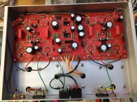
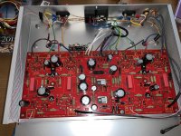
Here's a pic I took a while back during assembly. You can see the secondary wires - unconnected wires snipped at this point in the build. Not sure if I covered them with tape though...
The design appears to have push-pull feedback. With two feedback paths it is vital to ensure that the two paths are identical. Check component values, especially C9 and C15.
Good shout - just noticed on a picture I took during populating the board that one of those two capacitors is mounted higher up from the board than the other one (I think the leads were a tad tight for the holes). Perhaps any difference here (additional capacitance) could cause this?
Can potentially check the solder connections too.
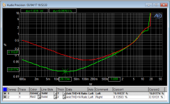
My DCPP has somewhat lower THD% than Pete's example (at 10W mine is ~1%, his a hair over 2%), but as illustrated below the two channels differ:
That's interesting and good to know. All I have is a picoscope to measure THD and I can never be sure if I've the FFT set up correctly.
Attachments
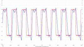
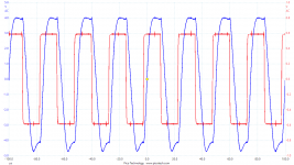
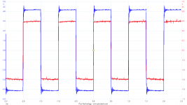
Eash... Check these out.What is your 1KHz & 4 KHz square wave output looks like. Looks to me one channel rings more than the other.
1k, 4k & 40k square waves - taken using 0.6Vpp (~1W output for a sine wave) input, output in to 8ohm.
Where do I start? I chop-sticked about the two capacitors C9 & C15 inside the plate-to-plate loop. Also moved the NFB wire from the speaker terminal back to the board. No change in the wave...
Attachments
Oscillating at 128kHz?
Is that from estimating the period atop the square wave?
I'll stick a scope on the speaker terminals with no signal and see if there's anything going. Then put 1kHz and focus in on the shorter timescale. Perhaps for a FFT up to 200kHz and see if there's a spike anywhere.
I notice that the frequency response plots in post 1 show a slight rise in the left channel at the same frequency as the right channel has a dip. It may be the same effect, but of opposite polarity.
Good spot. So something oscillates at some frequency when either left or right channel is excited at ~40kHz.
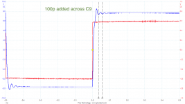
Change C9 and C15 value might reduce the right channel ring a bit (ie: Change it to 1000pf. See if that reduce the 40KHz notch.
That should be possible - can clip in 100p then 220p without removing the board to test.
Thanks for all the input.
Is that from estimating the period atop the square wave?
Yes
I am working on one project at the moment, but will put the DCPP on the bench in a day or so.
Must be a small phase difference between the two drive paths. Since you have a dual channel scope, disconnect the NF, apply say 20KHz to the input and measure the phase difference first on the plates of the phase splitter and then move to the output stage.
The circuit is slightly unusual in the R30/C7 R31/C10 seem to form some sort of bootstrap for the first stage. Certainly I would not be placing caps across the output transformer primary. Maybe repeat the test without these present.
The input needs to be driven from a low impedance to stop miller capacitance.
Last edited:
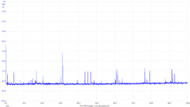
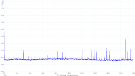
I went looking with the FFT - plots attached. With the amp in situ (speakers connected, preamp connected and muted) I hooked a scope probe tip to the +ve and ground to -ve connections at the speaker. I.e., after a few meters of cable. What do you reckon of the spikes? I couldn't see anything obvious going up and town the timescales at max vertical sensitivity.
Thanks - this is really useful. The pico's AWG output impedance is 600ohm in to the amp's 100k. My preamp has a really high input impedance (>1meg) and ~200ohm output.Must be a small phase difference between the two drive paths. Since you have a dual channel scope, disconnect the NF, apply say 20KHz to the input and measure the phase difference first on the plates of the phase splitter and then move to the output stage.
The circuit is slightly unusual in the R30/C7 R31/C10 seem to form some sort of bootstrap for the first stage. Certainly I would not be placing caps across the output transformer primary. Maybe repeat the test without these present.
The input needs to be driven from a low impedance to stop miller capacitance.
Here's what Pete wrote about those components:
I can do some scoping without removing the board (which would be a pain but seems inevitable). In order, taking sweeps / view square wave after each step, I can:There is local feedback around the output tubes, in the form of plate-to-grid feedback (ala Schade) of about 10%. It's implemented as resistors from the plates of the output tubes to the plates of the driver tubes (the 220k resistors R29 and R47 above). This linearizes the output stage and provides a reasonably low output impedance of about 2.8 ohms (without loop feedback). You see small caps (820pF) from plate to GND to optimize square-wave response in the feedback path.
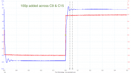
- Clip in an extra 100p across each cap in turn, then both
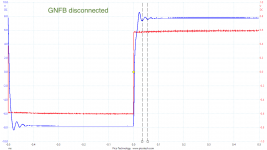
- Disconnect NFB
- Scope driver plates and compare phase
- Scope outut grids and compare phase
- Reflow the joints around the components in question
- Remove/replace capacitors based on 1
- Inputs / outputs / IEC moved to a rear panel
- Toroidal PT (the Edcor buzzed too much and got way too hot for my liking)
- Tag strip takes heater supply and rectifies for LED power indicator
- Inputs moved next to each other, so one run is longer than the other
Attachments
Last edited:
Sorry understud its local NF rather than bootstrap. I would have isolated the 820p from the transformer by splitting the 220k resistor. Anyway disconnect all feedback and look at the phasing of both drive signals. Just wondered if the 820p might resonate with the leakage inductance of the transformer. You may be better placing a very small cap across the 220k instead and have a zero - don't know.
Does the notch move up in freqeuency if you make the 820p say 470p.
Yes a high impedance into the first stage may affect the HF response - however its a pentode so the miller cap should not be an issue.
Does the notch move up in freqeuency if you make the 820p say 470p.
Yes a high impedance into the first stage may affect the HF response - however its a pentode so the miller cap should not be an issue.
Last edited:
What a frustrating day.
Thanks - I did what I could, described below.
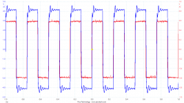
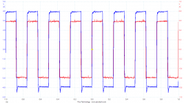
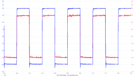
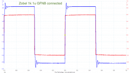
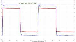
Getting annoyed I tried one last thing before firing up the soldering iron - a Zobel on the OT secondary. Used an RC decade box I twiddled the knobs to try and stop the ringing. Had a little success with 1k & 1u in series with no GNFB. Then connecting the GNFB made the ringing more obvious. Plots attached.
Struggling to interpret what's going on...
I measured the ringing - it came out around 41kHz
Anyway disconnect all feedback and look at the phasing of both drive signals. Just wondered if the 820p might resonate with the leakage inductance of the transformer. You may be better placing a very small cap across the 220k instead and have a zero - don't know.
Does the notch move up in freqeuency if you make the 820p say 470p.
Thanks - I did what I could, described below.
- Disconnect GNFB Ringing still here - attached
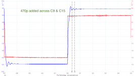
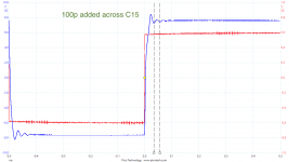
- Clip in an extra 100p across each cap in turn, then both Hardly any difference with 100p clipped in across C9 & C15, then C9 only, then C15 only. I then clipped in 470p across C9 & C15.
- Scope driver plates and compare phase Voltage too high for picoscope I think...
- Scope outut grids and compare phase Couldn't see any difference in phase looking at a 1khZ sine wave at the grids...
Getting annoyed I tried one last thing before firing up the soldering iron - a Zobel on the OT secondary. Used an RC decade box I twiddled the knobs to try and stop the ringing. Had a little success with 1k & 1u in series with no GNFB. Then connecting the GNFB made the ringing more obvious. Plots attached.
Struggling to interpret what's going on...
Attachments
Disconnect all NFB on both channels. Then work through from input until you see a difference - you can use a cap in series with your scope and 1M to ground if DC voltage too high or go on grid of final valve.
The only other thing maybe a faulty transformer having tried everything else could you swap them over?
The only other thing maybe a faulty transformer having tried everything else could you swap them over?
Last edited:
Rather than worrying about the frequency response the THD on the right channel climbs as the signal level reduces badly. This is probably crossover distortion. If only one half of a output stage is properly working you may well see ringing. Check TP6 and TP3 but also check the resistors. They can go O/C if a valve went short. Check R9 and R10 too.
Last edited:
Are you using the pictures in post 7 to determine the slew rates? DCPP - 'notch' in frequency responseThe slew rates are very different for the two channels, something is very different between them, perhaps a wrong value resistor, or dry solder joint, very different bias points, bad tube.
I think there's a period of desoldering / reflowing ahead. Will also try another set of driver valves.
Yeah - desoldering is needed to completely remove the NFB so will likely do it in stages.Disconnect all NFB on both channels. Then work through from input until you see a difference - you can use a cap in series with your scope and 1M to ground if DC voltage too high or go on grid of final valve.
That might be an easier one to test first off...The only other thing maybe a faulty transformer having tried everything else could you swap them over?
Rather than worrying about the frequency response the THD on the right channel climbs as the signal level reduces badly. This is probably crossover distortion. If only one half of a output stage is properly working you may well see ringing. Check TP6 and TP3 but also check the resistors. They can go O/C if a valve went short. Check R9 and R10 too.
Thought it would be worth posting my voltages - pretty close between channels and mostly in line with Pete's apart from my driver plate voltages are higher.
Attachments
- Status
- This old topic is closed. If you want to reopen this topic, contact a moderator using the "Report Post" button.
- Home
- Amplifiers
- Tubes / Valves
- DCPP - 'notch' in frequency response