Pete explained somewhere in the long thread about these boards that the 820 pF caps were added to cleanup the square waves on his amp. I built several of these amps and did not place the caps on any of them, but I used some 6600 ohm OPT's that I had.
The caps in this amp will see twice the B+ voltage in normal operation, more when driven to clipping into a reactive load. I have run these amps to 650 volts and driven them well beyond clipping with a guitar preamp without issue. I knew from the start that I would be doing that, so I left out limiting factors like these caps. Maybe Pete wired them this way to use common caps instead of HV caps. You also need to watch the voltage rating on the LNFB resistors. At these power levels they are probably OK, but they are seriously over voltaged beyond 50 WPC. In a similar design I had one flash over at 160 WPC into a resistive load.
I have found a Hammond OPT with mismarked wires plate, and UL wires swapped. Maybe Edcor can do this too. Swap your blue and brown primary wires, maybe your feedback is positive. Measure the resistance of each transformer's primary including the UL wires.
Just a thought.....reroute that pink feedback wire away from the input jack.
1. Why are those 820pF caps connected from each primary tap to ground?
The caps in this amp will see twice the B+ voltage in normal operation, more when driven to clipping into a reactive load. I have run these amps to 650 volts and driven them well beyond clipping with a guitar preamp without issue. I knew from the start that I would be doing that, so I left out limiting factors like these caps. Maybe Pete wired them this way to use common caps instead of HV caps. You also need to watch the voltage rating on the LNFB resistors. At these power levels they are probably OK, but they are seriously over voltaged beyond 50 WPC. In a similar design I had one flash over at 160 WPC into a resistive load.
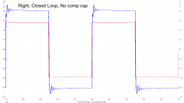
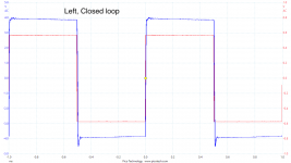
With only LNFB connected there is no ringing.....When applying GNFB the ringing appears
I have found a Hammond OPT with mismarked wires plate, and UL wires swapped. Maybe Edcor can do this too. Swap your blue and brown primary wires, maybe your feedback is positive. Measure the resistance of each transformer's primary including the UL wires.
Just a thought.....reroute that pink feedback wire away from the input jack.
You also need to watch the voltage rating on the LNFB resistors. At these power levels they are probably OK, but they are seriously over voltaged beyond 50 WPC. In a similar design I had one flash over at 160 WPC into a resistive load.
You don't want to use carbon composition in these positions -- they have a negative voltage coefficient (-50ppm/V) above 250V.
https://ws680.nist.gov/publication/get_pdf.cfm?pub_id=9237
You don't want to use carbon composition in these positions....
And they can fail in a flaming manner that often scatters burning pieces when the break down at high voltages. The words "carbon arc lamp" come to mind.
They made a minor difference to the square waves - but not of the order needed to take off the ringing I am seeing - I posted a few plots of this in post 38.Pete explained somewhere in the long thread about these boards that the 820 pF caps were added to cleanup the square waves on his amp. I built several of these amps and did not place the caps on any of them, but I used some 6600 ohm OPT's that I had.
See the new plots attached - I assume that I have the OT connected 'correctly' as the FB is negative, ie 6dB less than open loop.I have found a Hammond OPT with mismarked wires plate, and UL wires swapped. Maybe Edcor can do this too. Swap your blue and brown primary wires, maybe your feedback is positive. Measure the resistance of each transformer's primary including the UL wires.
I measured the resistances and they are very close between the two OTs, even down to the slight difference between the two halves. However, I forget if the reading between, say, blue and red is the constant across the two. or if they are swapped - will check this.
Yeah, I tried that - moving that wire entirely out of the way and even wrapping a grounded wire around it to provide a little shielding. No difference.Just a thought.....reroute that pink feedback wire away from the input jack.
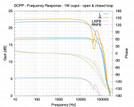
So I was busy the other day and re-took some readings all of the problem right channel:
- Frequency response sweeps at 1W output, sine wave input.
-- Open loop
-- Closed loop
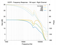
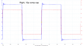
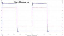
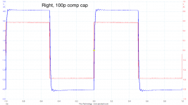
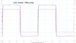
-- Closed loop with increasing compensation caps in the GNFB
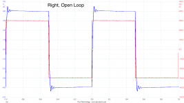
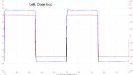
- 1kHz Square wave scope traces relating to those comp caps.
Also attached are open, closed and 100p traces for the left channel.
Not sure what to make of this. In summary:
- the ringing appears with both existing and entirely different OT: Not the OT
- the ringing isn't there with output tubes removed: not the driver stage
- the ringing is there with open loop, made larger with closed loop: expected?
- a compensation cap on the GNFB seems to help reduce the ringing at the expense of frequency response: expected, but seems a band aid rather than a solution?
Would a resistor cause the ringing? Or could it be the coupling caps?
Attachments
-
 DCPP-Sweeps.png107.3 KB · Views: 70
 -
 DCPP-Sweeps-Caps.png104.8 KB · Views: 71
 -
 Right-open-1W.png50.1 KB · Views: 73
 -
 Right-closed-1W.png52.7 KB · Views: 71
 -
 Right-10p.png49 KB · Views: 73
 -
 Right-68p.png49.5 KB · Views: 34
 -
 Right-100p.png48.8 KB · Views: 36
 -
 Left-open-1W.png48.2 KB · Views: 25
 -
 Left-closed-1W.png47.1 KB · Views: 28
 -
 Left-100p.png48.8 KB · Views: 36
OK, this has stumped a few of us for quite some time.....so I resorted to some good old Big Dumm Blonde One troubleshooting.
I picked up a partially built big red board from my unfisished projects box and compared it to the photograph in post number 5.....
either I have C4 in backwards, or you do! It's the smaller of two electrolytics between the output tubes.
I picked up a partially built big red board from my unfisished projects box and compared it to the photograph in post number 5.....
either I have C4 in backwards, or you do! It's the smaller of two electrolytics between the output tubes.
either I have C4 in backwards, or you do! It's the smaller of two electrolytics between the output tubes.
Thanks for your efforts George. That photo was taken just after I assembled the amp a few years ago. I spotted the error on final check, swapping it round. So the later post with an internal photo, it’s shown correctly.
Good eyes though!
OK its a sharp notch. Do you think the amp has always had this notch in the right channel.
Things to check - can you see the 40KHz on any of the supply or screen grid supplies. Your looking for a peak in amplitude as you sweep from say 10KHz to 100KHz. Maybe one of the decoupling caps is not working.
The other thing could be a PCB tracking issue in that some of the output current has made its way back into the input say by placing the ground of C3 so that it induces current into W27 ground. Its a bit like a hum loop. What I'am saying is that maybe the amp has always had this issue - its just you have discovered it.
The notch does not affect the NFB in any way - so I wonder if there is a PCB tracking issue on return currents.
Its difficult to tell on your open loop waveform but the current into W3 may well have that ringing waveform on it. The clue will be the ringing will be in the same direction for both positive and negative transitions. If C3 is near self resonant frequency it may return this current to the wrong ground say near the input and get this current through the input connector ground into the input stage.
Actually PCB looks good layout.
Last edited:
OK, I looked over the other picture VS my board and didn't see anything obvious......so much for BDBO easy mode....
There are a few electrical tests that could be done to rule out some things, or provide a few more clues.
1) Is the damping factor / output impedance of the two channels equal. Drive both channels with a sine wave to a low power level (5 watts or so) into a dummy load. Bridge a fixed resistor of about the same value as the load across the load and observe the output voltage drop. Do both channels drop by the same amount? Try this with and without GNFB. The LNFB affects the damping factor. Something messed up here can cause weird effects.
2) Probe each end of the balance pot in the bias circuit (R22 and R23) with a scope. Compare the two channels. There should be only DC here, an open or defective cap can upset the LNFB balance without affecting bias.
When normal troubleshooting / thinking doesn't work......
There is a dead part, a wrong part, or a defect in the board or construction. Bad solder joints or open plating, especially inside a hole, can be hard to find.
There are two channels, one works, one doesn't. The Dumm Blonde method would be to swap parts one at a time from one channel to the other until the defect moves. I assume that this has been done with the tubes. Parts swapping is not always easy, and sometimes messy. There are ways to narrow things down.
Are the DC voltages relatively close between the two channels, and between similar points in the same channel.
A simple but monotonous task is to measure all the resistors with an ohmmeter. The LNFB resistors (R29,R30,R31 and R47) get hammered pretty hard so I would start there. I had to use some rather big (physically) parts in the boards that I pushed to 125 WPC and beyond.
Resistance to ground measurements could provide a clue, especially if you find a point that differs from the other channel, or the same point in the same channel. I would start around the grids of the output tubes. Any significant difference should be followed to find the cause. A slight imbalance in the LNFB circuit can cause funny stuff.
A trick that I have often done is to divide and conquer. From what you have said the driver sections function OK without the output tubes present. I have often used drive from the good channel to drive the bad channel (actually both channels). In this case you would lift the plate ends of the coupling caps in the bad channel, and run jumpers from the lifted ends to the plates of the driver tubes in the good channel, thus driving both sets of output tubes from the good channel. That's a bit more complicated in your case since you used "box caps" for your coupling caps, and I used leaded tubulars.
Somewhere in the long build thread I stuck in some really big tubes and squeezed 250 WPC from the amp, then I performed this trick, and wired all four output tubes to a common (BIG) OPT for a 525 watt mono amp.
Thanks all for your comments - been unable to do much more on this for the last few days.
That being said, I have just liberated an unpopulated DCPP board from a fellow forum member in the UK (plus valves and sockets). It might be just as easy to order a new set of components from Mouser and start-over. Testing as I go. I'll use screw terminals for off-board connections like you did so removal is easier. This will be a longer-term project over winter if I can't spot and quick remedies with the tests above.
One thing I have noticed - through all this testing and switching on and off frequently, the new power amp valves I inserted in the problem channel have become rather noisy during warm-up. A few bangs through the speaker. Silent as usual after a few seconds. They didn't do this when 1st used...
Yeah - I checked back to my first frequency sweeps and it's there, although I was focussing on 10Hz-30kHz audio range I did spot ringing but thought nothing of it as the frequency response was flat.OK its a sharp notch. Do you think the amp has always had this notch in the right channel.
I'll check this. My analogue sig gen is very useful for this - tactile dials beat clicking options on screen!Things to check - can you see the 40KHz on any of the supply or screen grid supplies. Your looking for a peak in amplitude as you sweep from say 10KHz to 100KHz. Maybe one of the decoupling caps is not working.
This got me thinking - could solder flux left on the board allow current leakage? For this build I used some leaded solder acquired from an online auction site. And I recall it did leave quite a residue. I cleaned a bit of it off but quite a bit remains.The other thing could be a PCB tracking issue in that some of the output current has made its way back into the input [snip]
Actually PCB looks good layout.
Another one I'll check - I used isolating jacks but there's always a chance there's some contact.One other clutching at straws. If you have grounded your input phono connectors to the chassis you could have created a magnetic loop from the output transformer through the cable and back into the input.
George, this advice is great for anyone - particularly the resistance to ground measurements and comparing channel to channel. I'll do what I can.1) Is the damping factor / output impedance of the two channels equal. Drive both channels with a sine wave to a low power level (5 watts or so) into a dummy load. Bridge a fixed resistor of about the same value as the load across the load and observe the output voltage drop. Do both channels drop by the same amount? Try this with and without GNFB. The LNFB affects the damping factor. Something messed up here can cause weird effects.
2) Probe each end of the balance pot in the bias circuit (R22 and R23) with a scope. Compare the two channels. There should be only DC here, an open or defective cap can upset the LNFB balance without affecting bias.
A trick that I have often done is to divide and conquer. From what you have said the driver sections function OK without the output tubes present. I have often used drive from the good channel to drive the bad channel (actually both channels). In this case you would lift the plate ends of the coupling caps in the bad channel, and run jumpers from the lifted ends to the plates of the driver tubes in the good channel, thus driving both sets of output tubes from the good channel. That's a bit more complicated in your case since you used "box caps" for your coupling caps, and I used leaded tubulars.
That being said, I have just liberated an unpopulated DCPP board from a fellow forum member in the UK (plus valves and sockets). It might be just as easy to order a new set of components from Mouser and start-over. Testing as I go. I'll use screw terminals for off-board connections like you did so removal is easier. This will be a longer-term project over winter if I can't spot and quick remedies with the tests above.
One thing I have noticed - through all this testing and switching on and off frequently, the new power amp valves I inserted in the problem channel have become rather noisy during warm-up. A few bangs through the speaker. Silent as usual after a few seconds. They didn't do this when 1st used...
- Status
- This old topic is closed. If you want to reopen this topic, contact a moderator using the "Report Post" button.
- Home
- Amplifiers
- Tubes / Valves
- DCPP - 'notch' in frequency response