"Glad to hear it. You built the one in post #2?" Yes.
"Why no try something a bit more "exotic"" What are the advantages?
"Something like this... You can double check the values but I think they line up" Thanks Kod, same Q as above...
Having read the thread and the various articles linked etc there seems to be a few things I could try, bootstrapping to get more gain, IE cap from V2 cathode and split V1's anode load R, cap to junction of. (which it is, I'm using two 10k R's) That and terminate V2's cathode R's to V1's cathode, as in your schematic above, which gives AFAIK from the Broskie article better frequency response at low frequency.
A.
Why no try something a bit more "exotic"
Mona

Anode follower is old hat, it was used in audio gear in the 50s and 60s, like in the Dyna FM-1 and FM-3.
Also I used it in commercial products in the 70s and 80s. It does work well, and reduces the
output capacitor size needed, since it is within the nfb loop.
Last edited:
Not as simple as that.The common resistor for the cathodes is positive feedback, sort of alternative to a cathode decoupling.Gives more open loop gain making the negative feedback (output to input grid) more effective.Anode follower is old hat. It was used in audio gear in the 50s and 60s, like in the Dyna FM-1 and FM-3.
Also I used it in commercial products in the 70s and 80s. It doeas work well, and reduces the
output capacitor size, since it is within the nfb loop.
Mona
Not as simple as that.The common resistor for the cathodes is positive feedback, sort of alternative to a cathode decoupling.Gives more open loop gain making the negative feedback (output to input grid) more effective.
Mona
This was regarding the overall nfb loop, which makes it an anode follower.
I don't use positive feedback, and do not recommend it.
What are the advantages?
Having read the thread and the various articles linked etc there seems to be a few things I could try, bootstrapping to get more gain, IE cap from V2 cathode and split V1's anode load R, cap to junction of. (which it is, I'm using two 10k R's) That and terminate V2's cathode R's to V1's cathode, as in your schematic above, which gives AFAIK from the Broskie article better frequency response at low frequency.
A.
It provides more gain, and without bypassing the cathode.
Hmmm… odd direction, very small positive feedback.
As far as it goes, I think there's something to be said for turning the local NFB “off” by bypassing with a capacitor for more gain, or by choosing an appropriate LED with approximately the same nominal voltage drop as the resistor being replaced measures.
Now, finding the LED is a bit more tedious: I ended up taking my entire 'bag of LEDs' dating everywhere from the 1970s thru absolute-modern, breadboarding a constant-current source (resistor, JFET, 2 ea 9 V batteries...) on a IC project board, then hand-binning them by forward voltage drop at 10 mA. What a remarkable exercise!
I expected ALL the red LEDs to have close forward voltages. They did not. By brand, or rather by brand-and-part-number, yes. But still quite a bit of variability. After binning in ⅕ V bins, I just used tiny zip-lock bags to keep them separated, and a Sharpie on each bag to record the VF value. Now I don't have to guess!
Since the (hard to write) forward voltage-and-current equation for semiconductors is ALWAYS an exponential, the VF-vs-current really doesn't budge much in a ¹⁄₁₀x to 10× (i.e. 1 mA to 100 mA) current range. A few percent. Not enough to matter.
It should be noted that the gain-increase can be rather significant, once VK is rendered fixed instead of floating. It also should be noted that the amount of output signal distortion also substantially increases. Comme ci, comme ça.
Just Saying,
GoatGuy ✓
Last edited:
Sorry about my being VERY late to the "party". I've been battling computer woes and the emergency machine I'm using is slower than a snail. 
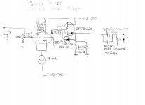
Going back to the OP's stated requirements of modest gain and substantial drive capability, I'm uploading a 6SN7/MOSFET hybrid. Because the differential gain block is driven at only 1 I/P, max. thoretical gain is 1/2 mu. Resistive loading reduces gain to < 1/2 mu. So, gain is < 10. The setup is non-inverting, extremely linear, and has gargantuan drive capability.
It should be noted that low O/P impedance, while necessary, is not sufficient. Current handling ability sufficient to charge and discharge interconnect cabling capacitance is necessary too. IMO, prefer 5687, ECC99, etc. over 6922, in the cathode follower role. A big, honking, MOSFET has even more "stones".
Attachments
@ eli …
Yes, of course. That's one heck of a watt-burner, that. The 24.9 kΩ resistors are each conducting about 2.1 to 2.5 watts quiescent. Not much different when pre-amping the signal, of course. But it looks good. And the 'trivial thing' as long as burning watts is of no consequence, is to use an even lower source load resistance, by perhaps just paralleling even more of the 2.5 watt heaters. Go as low as you feel like warming the environment.
The MOSFET definitely has “the stones”. I've been avoiding referring to them tho', as this is the tube forum and as we don't have a steampunk hybrid forum under which such ideas really aught be held.
Still … good alternative.
Solid.
One could even get away with a bit of negative feedback to further tame distortion and over enthusiastic gain at one go. There's that nice right-side grid-to-ground on the dual triode which presents obvious opportunities.
Just Saying,
GoatGuy ✓
- Status
- This old topic is closed. If you want to reopen this topic, contact a moderator using the "Report Post" button.
- Home
- Amplifiers
- Tubes / Valves
- Line preamp questions.