Yes, but couldn't you use pentodes to achieve the same result?
Still not the 40M to 60M with cascode MOSFETs. And the "sand" CCS can do that with 20-30V plus required signal swing. A pentode will need a lot more voltage to operate. Will require a negative supply for the cathode follower.
I get you. This MOSFET CCS could be a DN2540 or 10M45S or 10M90S, yes? Could you make one with a combination like TIP41 and TL783?
Sorry, but I really only know tubes and by extention, depletion devices.
I'm all in favour of using the best device for the job really. I wouldn't build using tube rectification unless I was specifically asked to do it for someone, for example. Still, there is a robustness to tube technology. What other device can take an overload like a tube and live to work another day? OTOH, I once had a 6P45S run away that got so hot as to fracture the glass! The amp sounded fine until I heard that sound, then the amp got twice as loud (because the voltage went back up to normal for the rest of the amp. To make a 6P45S hot orange would require amperes! The transformer was rated to deliver it (572VA for a 100W mono amp)).
Last edited:
I thought so. Does that mean it's 1/2*mu unbypassed, and higher if it is?
All the factors cancel out to give mu/2 only if Rk and mu are equal for the top and bottom sections.
You'd have to calculate the gain from the general circuit equation for cases where the two
cathode resistors are unequal in signal terms. See page 464 in Valley and Wallman for the
general case equation, but setting Epp (supply voltage) to zero to get the signal gain.
Last edited:

But Rk is still equal, just one is bypassed, the other is not. I take it that math gets VERY complicated.
The cathode resistors must be equal in signal terms. If one Rk is bypassed, they are not equal as far
as the signal is concerned. It just takes the usual Kirchhoff circuit algebra to get the gain equation.
Last edited:
I'll second the recommendation for the Broskie CCDA circuit. I used the 6922, with 250V B+, 24K9 first stage anode and second stage follower resistors. First stage 634R cathode resistor. I include the 100R buffer resistor shown as R7 on Broskie's schematic. I also changed the output cap to 2.2uF for driving loads such as 50K. I used a CLCLC power supply filter section.
I like it a lot. Sounds great, no noise.
Forgot to mention that I did not bypass the first stage cathode resistor, but put in a switch to bypass with 100uF if additional gain is needed.
I like it a lot. Sounds great, no noise.
Forgot to mention that I did not bypass the first stage cathode resistor, but put in a switch to bypass with 100uF if additional gain is needed.
Last edited:
I get you. This MOSFET CCS could be a DN2540 or 10M45S or 10M90S, yes?
IME those suck. Try IXYS 8N50D2 on the bottom and either 8N50D2 or 8N100D2 on top. The '50 is rated for 500V and the '100 1,000V. Kevin Carter at K&K Audio sells kits that are cheap and convenient. Makes it easy to try. If you don't like the results you're not out much, money or time.
I'd add to that a low mu tube on top. Much less stray capacitance coupling to B+.... Try IXYS 8N50D2 on the bottom and either 8N50D2 or 8N100D2 on top. ...
All the factors cancel out to give mu/2 only if Rk and mu are equal for the top and bottom sections.
You'd have to calculate the gain from the general circuit equation for cases where the two
cathode resistors are unequal in signal terms. See page 464 in Valley and Wallman for the
general case equation, but setting Epp (supply voltage) to zero to get the signal gain.
Ideally both triodes should have equal voltage gain and GM. That's only obtained from triodes with equal Rp. So, don't match tubes for mu only.
Read the thread through again, a few questions... Why use a mosfet in a CCS instead of a BJT? I usually use a MJE340/350, zener to set BE voltage, usually 6V2 then a fixed R and preset to set current.
Regarding using a battery to set bias of 1st valve, I would have thought the battery would be wired from g1 to cathode, does AC flow through a battery?
Anyroad, will go and knock up the circuit with resistors first, then fiddle with it after if needed.
A
Regarding using a battery to set bias of 1st valve, I would have thought the battery would be wired from g1 to cathode, does AC flow through a battery?
Anyroad, will go and knock up the circuit with resistors first, then fiddle with it after if needed.
A
Regarding using a battery to set bias of 1st valve, I would have thought the battery would be wired from g1 to cathode, does AC flow through a battery?
In the shown schematics the battery indeed is between g1 and cathode, through the potentiometer.
Anyway, I'd feel somewhat uncomfortable with the input AC signal flowing through it. Why not put a rechargeable cell of appropriate voltage in a position where impedance is much lower, i.e. between cathode and ground?
Best regards!
In the shown schematics the battery indeed is between g₁ and cathode, through the potentiometer. Anyway, I'd feel somewhat uncomfortable with the input AC signal flowing through it. Why not put a rechargeable cell of appropriate voltage in a position where impedance is much lower, i.e. between cathode and ground? Best regards!
… because it would become overcharged, then exhibit its perhaps spectacular failure modes.
The right answer (for the ground-to-cathode bias position) is to use something which shows a near-fixed-voltage (even a battery is only 'near-fixed', not completely so). So far, us tinkerers have come to appreciate the lowly LED diode.
LEDs have a forward voltage drop that is almost a constant over a fairly large range of current-flows thru them. The VF depends on many factors, but is related both to the color of the LED's characteristic glow, and the particular processing given to it in manufacture. Red LEDs almost always are lower voltage than green, green less than blue, and blue less than ultraviolet (or 'white', since white is UV→phosphor mediated).
The design criteria tho are simple enough. You work with the available VF forward voltage drops by using LEDs singularly or in series. Obtaining “some value”. Then, you go back to the anode-load side and recalculate that from the expected quiescent current flowing thru the valve given the -VF effective grid bias.
Note that exactly the same could be done with converntional small-signal diodes too. Not as colorful, but just as useful. Smaller VF per diode, only 0.7 V or so. Somewhat more temperature-related drift … which LEDs have better control over because of their optical bandwidth engineering (i.e. color stability over wide temperature range). But small signal silicon diodes definitely could be used in strings. They take more amperage too… in general.
I once did a 'switchable cathode bias' using a string of conventional 1N4007 diodes on a single-ended-triode power output stage, using a rotary selector. I had determined experimentally that I needed a bias of 'about' 17 V. But that it could range from 14 to over 24 for various tube substitutions. So, a 12 position rotary switch got the job done. String-of-diodes giving 15 V leading to it, another string of 11 around the edge, and the wiper to cathode. Worked like a charm. Also installed a top-side-of-chassis pair of insulated test points with a 1.0 Ω resistor in series to cathode … to measure current and quiescent voltage easily. Always nice having test points.
Oh, having dedicated current and voltage analog meters is also nice … but unnecessary most of the time.
Anyway, an old timer's ramblings.
Just Saying,
GoatGuy ✓
Why use a MOSFET in a CCS instead of a BJT?
Mmmm… mostly because hi-V MOSFETs are plentiful, cheap, and really easy to build CCS's out of, I would venture. … DN2540, for example. VGS at 25 mA of about –1.2 V. Makes for easy setpoint. RCATH = 1.2 / ITARGET. VDSMAX = 400 V, too.
Just Saying,
GoatGuy ✓
PS ... though, unlike true constant-current regulators (which are temperature-and-manufacturing-variance compensated 'chips' with even stronger cut-off conditions), you really do have to measure the actual current flow with a standard 100 ohm resistor, then use that to jigger the predicted R value. A wee bit more work, but saves you about a buck or two.
Last edited:
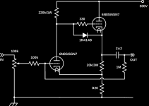
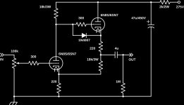
I do the same but using triodes instead of MOSFETs. In the example I posted, you'd replace the 20k resistor with another 6CG7 like in this example. It uses twice the number of tubes, but moves most of the waste heat above the chassis allowing for a small, hole-less enclosure.
You can also connect the bottom output tube grid to input instead of to ground. Gives reduced Rout. With a transformer input (low resistance for DC) you can even go positive.
Broskie reserved that tube for Aikido-PS feedback . . . But in the way I describe it, it has great standard triode sound (harmonics). (In L'Audiophile', Franch magzine, early '80ies, there was a nice design with this.)

Last edited:
"In the shown schematics the battery indeed is between g1 and cathode, through the potentiometer." Aye, I was aware of that, I was thinking as you later suggested with the battery in parallelrather than series so to speak
Knocked this up yesterday and gain was very disappointing, EG 500mV in, 1v out, HT/B+ was 300v. The circuit might not be working correctly though, the first valve is biased at Vgk - 3.3v, second valve , Vgk is -0.7v. this is the circuit with no current sources, one valve only as in post #2
Andy.
Knocked this up yesterday and gain was very disappointing, EG 500mV in, 1v out, HT/B+ was 300v. The circuit might not be working correctly though, the first valve is biased at Vgk - 3.3v, second valve , Vgk is -0.7v. this is the circuit with no current sources, one valve only as in post #2
Andy.
Last edited:
After re-seating the valve - 6CG7 into the valve base and re-cheking connections OP is more like it - 5.5v RMS. With 300v HT V1 is biased at Vgk -3.1v, and V2 at Vgk -3.6v. Frequency response is essentially flat from 100hz to 20khz (quick sweep) and THD is 0.5% @ 1khz @ 5.5v RMS OP and is pretty much the same at 10khz but goes up a tad at 100hz to 0.7%. this is mostly 2nd H with a bit of 3rd.
With a square wave IP it's looking good from 1khz to 10khz, there is some HF loss at 100hz though. however my sq wave source isn't brilliant. I put a 15p cap on the OP, no change i the OP sine at all, which bodes well.
The last test I did was reduce HT, OP fell by only 0.6v RMS at 100v.
So am pretty impressed with the circuit. I don't know as I'll bother with CCS's but might try a couple of LED's in V1's Rk spot. The circuit as is performs well, any improvement is just guilding the lily and adding extra complexity for diminishing returns.
Andy.
Why no try something a bit more "exotic"Knocked this up yesterday and gain was very disappointing, EG 500mV in, 1v out, HT/B+ was 300v. The circuit might not be working correctly though, the first valve is biased at Vgk - 3.3v, second valve , Vgk is -0.7v. this is the circuit with no current sources, one valve only as in post #2

Mona
Attachments
- Status
- This old topic is closed. If you want to reopen this topic, contact a moderator using the "Report Post" button.
- Home
- Amplifiers
- Tubes / Valves
- Line preamp questions.