Have made a 6 times voltage multiplier power supply for a 6cm5 amplifier. Output stage is done but i have a question. The last two capacitors in the multiplier are rated 450 volts. When i first turn the amp on the B+ reaches 505 volts DC , for few seconds. Will this damage the Capacitors ? And also will the two last capacitors each have 505 volts or will it be shared ? Thank you
Diode-capacitor multipliers (Cockcroft-Walton) have constant voltage rating along the chain, so for long chains the device voltage rating will be less than the total voltage - basically everything's in series and the voltage rating depends only on the input AC voltage.
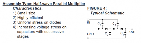
Several voltage multiplier topologies are available. The 1/2 wave serial multiplier described has substantial stage to stage losses. Cost is its principal advantage. The uploaded 1/2 wave parallel topology is much better for a B+ supply, with far smaller losses. In the parallel case, increasing voltage stress, stage by stage, on the caps. is present.
Lots of good info. is available on Voltage Multipliers Inc. web site. The upload was extracted from that site.
Attachments
I´d use 2 x 350V rated capacitors in series for the last stages; that´s what tube guitar amp makers routinely do.
Not "audiophiles" by any means, but solid Businessmen, if they do that it´s because it allows them avoid expensive warranty claims, so I´d follow their advice.
Running stuff to the limit and trusting tolerances is not a good recipe.
Hey, speaking from own experience too: just last week a customer complained one of my 300W Bass amplifiers was smoking big time.
Asked for gut pictures and found that one 4700uF x 63V supply cap had blown its top and steamed out with mere 60V supply, go figure.
Mind you , they are a generic brand (Suntan) and always use them with no trouble ... until last Friday that is.
So in principle: working too close to ratings is "barely enough"; surpassing them is bad engineering, even if sometimes you can get away with it.
If you do this it's usually recommended to put balance resistors across each cap in series. One paper on the subject from Illinois Capacitor recommends
R (in megaohms) =10/C (in uF)
Eg. for 47u
R = 10/47 = 0.21 Meg = 210k
220k near enough
Rating for 225v gives 0.23W. Better use 0.5W or more to have a good margin.
By this formula, larger caps need lower resistance and therefore burn more power and need a higher rating.
If you can match the capacitors well and overrate them (eg. Use 2 x 450v caps) you can probably get away with higher value balancing resistors as getting the balance exact won't matter as much.
Keep in mind also that total capacitance is halved when you put two like caps in series. So to make one 47u you'll need 2 x 100u .. etc
I know what he said and I don't find it clear. It seems to me that there may be no problem to solve here.
Agreed. The OP could in fact answer his own original question "And also will the two last capacitors each have 505 volts or will it be shared ?" by measuring the voltages across each of the two capacitors separately.
By this formula, larger caps need lower resistance and therefore burn more power and need a higher rating.
If you can match the capacitors well and overrate them (eg. Use 2 x 450v caps) you can probably get away with higher value balancing resistors as getting the balance exact won't matter as much.
As a worst-case approximation, you can assume that one capacitor has its specified maximum leakage current while the other doesn't leak at all. You can then calculate what balancing resistors are needed to keep the voltage across the capacitor that doesn't leak below its maximum rating.
Thank you guys for the good advice . Plan is to build a P P 6cm5 fixed bias amplifier. I built one using cathode bias but its simply not working out well And i haven't ever been able to find a cathode biased 6cm5 circuit anywhere. So .. figured fixed bias be better plan.
Max. plate dissipation for the 6CM5 is 10 W. I see no reason why self bias can't work. Look into 6GW8 based designs. The power pentode in the 6GW8 is rated for 9 W. of plate dissipation and the triode is "equivalent" to those in the 12AX7.
FWIW, I suggest full pentode mode with g2 B+ regulated by a stack of 2X 0B2s. Some liberty can be taken with the max. allowable plate B+, IF plate dissipation is scrupulously kept within the published limit. Heat, not mere volts, is what destroys tubes.
- Status
- This old topic is closed. If you want to reopen this topic, contact a moderator using the "Report Post" button.
- Home
- Amplifiers
- Tubes / Valves
- Voltage Multiplier Capacitors