EJP...Thats exactly what i was wondering about. Do the last two capacitors EACH cop 505 volts ? From what you said i should measure voltage at start up on each cap individually to know the answer .
The last two caps in my circuit are 450volt rated.
As to the Cathode biased idea i believe the 6cm5's can handle a lot more than 10 watts diss. Some say they wont red plate till about 25 watts diss. I don't know what maximum plate voltage they can handle. So what cathode current and plate voltage in a cathode biased situation to aim for i simply dont know.
That's exactly what *we* were wondering about. I asked a clear question. Only you can answer it. I don't know what exactly you mean by 'last two capacitors' or even '505 volts' at the moment, as you haven't stated where it was measured or what it was referenced to, or whether you are including the capacitors for HT2/3, but none of the capacitors in the schematic has the full HT1 rail voltage across it.
Sorry EJP i thought my question was clear enough. By the last two capacitors i meant the very last two in the 6 times multiplier C3 and C6 , which on the circuit are marked as 250volt types. The ac supply is 55vac. The B+ is at The C3 + (also marked as HT1).
I was curious about the voltage rating when i saw 505 volts dc at the B+ Hence the question.
I was curious about the voltage rating when i saw 505 volts dc at the B+ Hence the question.
Sorry EJP i thought my question was clear enough. By the last two capacitors i meant the very last two in the 6 times multiplier C3 and C6 , which on the circuit are marked as 250volt types. The ac supply is 55vac. The B+ is at The C3 + (also marked as HT1).
I was curious about the voltage rating when i saw 505 volts dc at the B+ Hence the question.
A schematic would be worth a thousand words!
I'm still unclear why you haven't answered your original question by simply measuring the voltage across each of the final capacitors.
Sorry EJP i thought my question was clear enough. By the last two capacitors i meant the very last two in the 6 times multiplier C3 and C6 , which on the circuit are marked as 250volt types. The ac supply is 55vac. The B+ is at The C3 + (also marked as HT1).
I was curious about the voltage rating when i saw 505 volts dc at the B+ Hence the question.
We definitely need a schematic and/or measured voltages across individual capacitors to make any useful comments. The only schematic in this whole thread, the one attached to post #6, doesn't even have a C6.
The circuit is the same as the Valve heaven Lamington 2 . I havent been able to post it . But it is a standard common 6 times multiplier. With 250 volt rated capacitors. This is why i was curious about the 505 volts at the B+ and (at the last two capacitors ) . Sorry i can't explain it any better than that ! I will measure the voltages at those two capacitors.
The circuit is the same as the Valve heaven Lamington 2 . I havent been able to post it . But it is a standard common 6 times multiplier. With 250 volt rated capacitors. This is why i was curious about the 505 volts at the B+ and (at the last two capacitors ) . Sorry i can't explain it any better than that ! I will measure the voltages at those two capacitors.
If you mean lamington-power-supply | Valve Heaven then its a quadrupler, not a sextupler. With the 60V from the power transformer as in the schematic, and in the no-load case where HT1, HT2 and HT3 are not having any current draw, the voltages across C5 and C6 would both be a bit less than 340V. (They are both seeing the full output voltage, since they are coming after the output from the quadrupler itself, and they are essentially in parallel, in the no-load situation.)
But since you are saying yours is a sextupler, it would seem you must be meaning a different schematic.
Last edited:
Thank you cnpope . It is in fact a 6 times multiplier. as per the Lamington 2 . Other lamington power supplies are 4 times. With your calcualations that means 509 volts across each capacitor. And i guess thats why i saw 505 volts on the B+ at start up . The circuit has 250 volt capacitors , hence the question.
But not hence your complete failure to answer the questions you were asked here. Nobody except you has posted anything that suggests, or calculates, that there is anything like what you are claiming here. 505V B+ does not and cannot possibly imply 509V across every capacitor in this circuit, and specifically not the two 250V-rated ones. It is impossible. Hence the questions. Test and measure, and answer what you're asked. Instead of going off at a tangent and asking a whole lot of different questions.
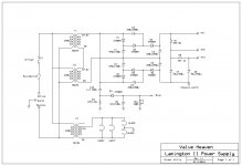
Here is the schematic for others reference. The OP referred to C3 and C6 in post #24. If B+ peaks at 505V then C3 and C6 would each see half of that, which is likely OK for a short term surge for 250V capacitors. Although I don't know why he still hasn't put a multimeter across each cap to prove it for himself.
Attachments
Thank you Tikiroo !
The reason i havent measured the individual caps with a multimeter is simple ...i haven't been home ..I am often away working.
Thank you Tikiroo for confirming what i though must be the case seeing the last two caps in the original circuit are only 250 volts.
The reason i havent measured the individual caps with a multimeter is simple ...i haven't been home ..I am often away working.
Thank you Tikiroo for confirming what i though must be the case seeing the last two caps in the original circuit are only 250 volts.
It seems a bit absurd that finally, 12 days after the original question was posed, we were presented with a schematic, not by the OP but by another member, so that we could see what C3 and C6 actually are, and so the question could be answered.
As always, a schematic is worth a thousand words...
As always, a schematic is worth a thousand words...
- Status
- This old topic is closed. If you want to reopen this topic, contact a moderator using the "Report Post" button.
- Home
- Amplifiers
- Tubes / Valves
- Voltage Multiplier Capacitors