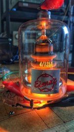
hi this is my testing 4-125a tube ht+1100v bias 50ma 6k opt
Saran audio - 4-125a class a. Test
กำหนดจุดทำงาน...
Saran audio - 4-125a class a. Test
กำหนดจุดทำงาน...
Attachments
is that triode wired?
It’s power tredtrode. Tube. I config in in tredtode mode run screen ccs controls voltage and current. Bias points don’t far away from -g 0v
hi this is my testing 4-125a tube ht+1100v bias 50ma 6k opt
Bias points don’t far away from -g 0v
What is the screen voltage ?
What is the screen voltage ?
Grid no 2 is around 325v 25ma
Last edited:
Stoppers? If not, you may find you have built a high power UHF oscillator and get an RF burn.
Ho. What’s am I wrong
i design it run class a /a1 in pentode mode ? The screen grid for controls gain and the anode current or not. If i’m wrong with that what the best way i can do. Such as ground the controls grids and used grid 2 as triode mode please advise
Thank
Putting a resistor on the G2, and maybe one on the anode (Some transmitting tubes state this on the datasheet) will stop/control unwanted HF/VHF oscillation. Put the G2 stopper as cose to the vaklve base pin as far as possible, try anywhere from 220 r up, about 100r on the anode if needed.
It's usual to use a stopper on the control grid G1 too, with a 10:1 ratio in reference to G2, EG 1k on G1, 100r on G2, or better 2K2 and 220r.
Andy.
It's usual to use a stopper on the control grid G1 too, with a 10:1 ratio in reference to G2, EG 1k on G1, 100r on G2, or better 2K2 and 220r.
Andy.
Last edited:
Putting a resistor on the G2, and maybe one on the anode (Some transmitting tubes state this on the datasheet) will stop/control unwanted HF/VHF oscillation. Put the G2 stopper as cose to the vaklve base pin as far as possible, try anywhere from 220 r up, about 100r on the anode if needed.
It's usual to use a stopper on the control grid G1 too, with a 10:1 ratio in reference to G2, EG 1k on G1, 100r on G2, or better 2K2 and 220r.
Andy.
Thank you. Very much
I will try again with your advice and report howit work
uhf starts at 300mhz, which this baby can´t do.Stoppers? If not, you may find you have built a high power UHF oscillator and get an RF burn.
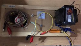
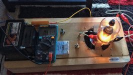
Nsaran, have look on this low power amp test, it was small success.
anode cooler was more important than glass cooling.
what i found -- you can use xmitter tubes under 1kv a1, but only as low current.
Last edited:
The 4-125a can do up to 300mhzuhf starts at 300mhz, which this baby can´t do.
See
http://www.tubecollectors.org/eimac/archives/4125a(47).pdf
300MHz is the modern start of UHF. Back when that valve was a new design, UHF started a bit lower. Most valves can manage to oscillate at UHF in the right circuit, whether accidentally or deliberately, as oscillation is typically the easiest thing to do for any technology - useful lowish noise or reasonable power amplification is at lower frequencies.
300mHz/mhz is a syllabic rate.
300mHz/mhz is a syllabic rate.
derating and losses starts rising above 120+, i think it will be not able to self oscillate that high.
very low steepness is another reason. it´s not a framegrid thingy
")
Attachments

As I said, for a given technology/device the ability to oscillate usually extends to higher frequencies than any other function. That graph seems to show that at 250MHz it has a gain in the region of 14dB. You only need a bit over 0dB gain to oscillate, so I would not be surprised to find one 'singing' at 500MHz. Of course, the OP might be lucky but it would be wise to treat high power valves with respect and be aware of possible hazards.
derating and losses starts rising above 120+, i think it will be not able to self oscillate that high....
"Ratings" don't matter, since any oscillation is an "accident", and cooking the tube just one of the consequences. (And it may be robust enough to sing >120MHz in home use, but not in 24/7 critical military work...)
Your own graph, interpreted, suggests small margin for singing at 330MC.
However I had understood "UHF" as "real high", not a specific page in ITA allocation tables. Lots of RF burns have happened at 27MHz etc, even with smaller tubes like 6146.
Attachments
DF96,
Everything that does not remain the same, is subject to change.
1. The 1947 Encyclopedia Britannica lists Microwaves as starting at 50 MHz.
When I first read that, I thought Wow!
2. Your Microwave Oven operates at 2,450 MHz,
that is 550 MHz less than 3,000 MHz.
3. Standards are such a wonderful thing, everyone has their own.
4. I am one of a few that has ever measured 500 GHz on an electronic
(not optical) spectrum analyzer. But that is a different story.
500 GHz is sub-millimeter microwave, but still a lot lower frequency than infrared light.
- Status
- This old topic is closed. If you want to reopen this topic, contact a moderator using the "Report Post" button.
- Home
- Amplifiers
- Tubes / Valves
- 4-125a class a test circuit