 HV reg posts split off to here:
Jan,
Would voltage delay increase the B+ more than 450V? Or it acts as on/off switch. I was looking at your circuit before but out of stock so I went on to buy different brand from ebay since I was lazy to build one from your document.
Right now, every time I turned it on, the delay works as it's support to but the first resistor in the circuit got smoke. I am planning to remove voltage delay to see if it causes the problem or something else.
--->--VD---B+---R1----R2: my R1 get smoke every time VD activates. It used to work before.
I don't understand where your R1 and R2 are. Is that part of your decoupling or what?
Which delay are you using now? The delay shouldn't do anything to the voltage, just connect its input to its output after some time. Are you sure you connected it right?
Can you post a schematic, even if a pic from your phone?
Jan
Which delay are you using now? The delay shouldn't do anything to the voltage, just connect its input to its output after some time. Are you sure you connected it right?
Can you post a schematic, even if a pic from your phone?
Jan
Thank you, that's I thought, I have 1 for each channel, used to work for a while. Happen only 1 channel. The other channel still works fine.
This is the one I have
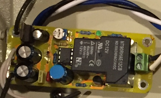
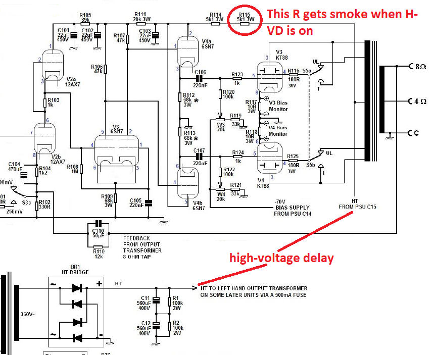
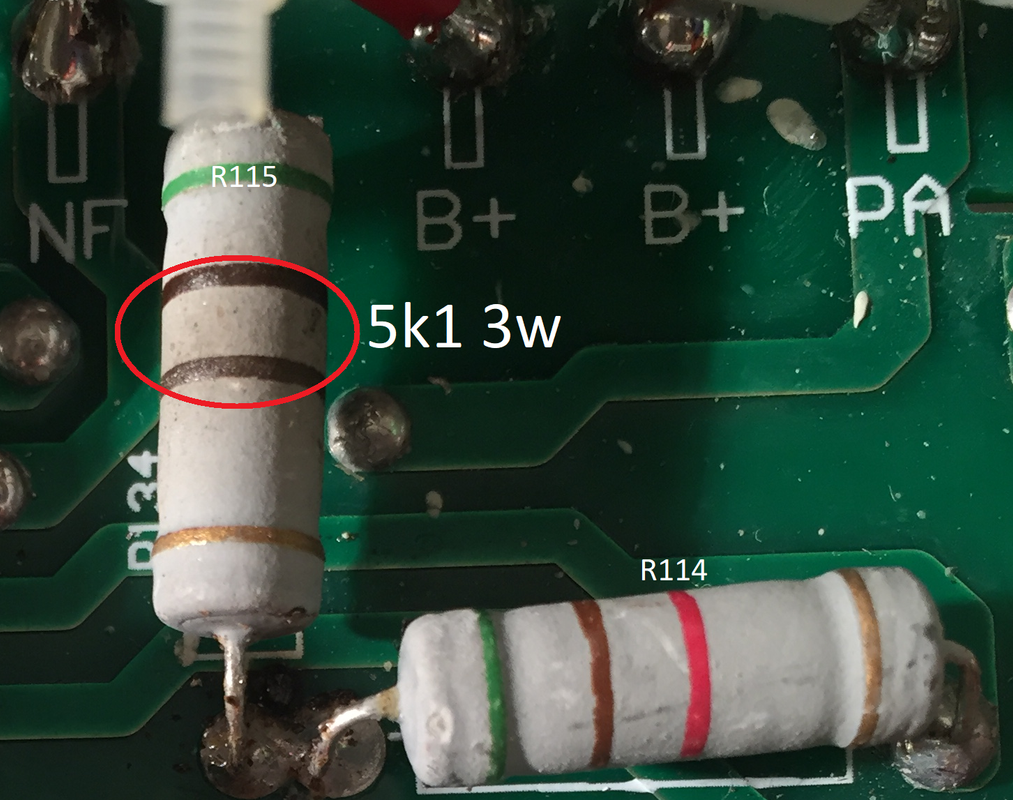
Then the first R (R115) comes out smoke when the H-VD starts. Even replaced new R still the same. I turned off right away so I am not sure where to start trouble-shooting yet.
This is the one I have
Then the first R (R115) comes out smoke when the H-VD starts. Even replaced new R still the same. I turned off right away so I am not sure where to start trouble-shooting yet.
That has nothing to do with the delay, you have a short to ground between R114 and R115.Thank you, that's I thought, I have 1 for each channel, used to work for a while. Happen only 1 channel. The other channel still works fine.
Then the first R (R115) comes out smoke when the H-VD starts. Even replaced new R still the same. I turned off right away so I am not sure where to start trouble-shooting yet.
Mona
That has nothing to do with the delay, you have a short to ground between R114 and R115.
Mona
I have checked many times between R114 and R115. Any points after R114 seem normal. I will check again later.
If the Output is bad, would it give the problem too since it connects to the Output?
The current comes for the output and to R114.Without a deviation all current from R115 goes throug R114 and that one would burn too.I have checked many times between R114 and R115. Any points after R114 seem normal. I will check again later.
If the Output is bad, would it give the problem too since it connects to the Output?
Mona
When R115 starts spark and smoke, I turn it off so R114 is fine. Even I raised the PCB up a little to make sure nothing touching the case. I compared with the working channel and couldn't find anything different. Did a lot of measurement to compare. At least H-VD is not the problem, I will take time again to check all the points with GND again.
Spark at the legs of R115 and R114
Spark at the legs of R115 and R114
I have checked many times between R114 and R115. Any points after R114 seem normal. I will check again later.
If the Output is bad, would it give the problem too since it connects to the Output?
A very simple quick check is to bridge the delay with a wire. If it still smokes, it isn't the delay. I agree with Ketje's diagnosis. If R114, R115 are slightly different (large tolerance), could be a shorted elcap: disconnect C103 and see if your trouble is over.
Although it could also be a shorted tube in that case.
Jan
Last edited:
 Oh yeah, why didn't I think to bridge the Delay instead of remove ..lol.. thanks that's an easy trouble-shooting.
Already swapped all the tubes from working channel but still the same.
Sorry, didn't mean to hijack your thread but it's very helpful in my case. I will start with C103 to see what happen.
R114 and R115 value pretty much the same.
I think I will start with C103 since I removed both R114 and R115 to do a measurement, the R114 has exactly value while the R115 value just a little slower than the R114 but not that much.
I haven't done removing R114 to power on yet. I will do that too. Actually, I don't have time to fix it right now since working to remodel the audio room. May take another 2 months to complete before I can setup and have time to work on it. Your info and others are great guide to start trouble-shooting. All I did was swapped the tubes, compared all the points from working channel, and replaced the R115. Haven't done anything you and others mentioned in here yet.
I haven't done removing R114 to power on yet. I will do that too. Actually, I don't have time to fix it right now since working to remodel the audio room. May take another 2 months to complete before I can setup and have time to work on it. Your info and others are great guide to start trouble-shooting. All I did was swapped the tubes, compared all the points from working channel, and replaced the R115. Haven't done anything you and others mentioned in here yet.
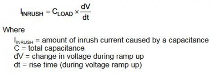
Did some more searching about the cathode stripping effect and found the attached. Sounds plausible.
An argument you often hear is 'I own a 1962 radio with original tubes and it still plays fine'. But these old radios had tube rectifiers and therefor build-in high voltage delay. So this is really an argument showing the benefits of high voltage delay ...
Jan
An argument you often hear is 'I own a 1962 radio with original tubes and it still plays fine'. But these old radios had tube rectifiers and therefor build-in high voltage delay. So this is really an argument showing the benefits of high voltage delay ...
Jan
Attachments
Yes I read that the other day - it is just conjecture.
That said, there certainly are many examples of output stage valves, and perhaps to a lesser extent preamp valves that show a walk-away effect of grid voltage in a typical circuit with just grid leak resistor. Measuring the anode voltage whilst shorting the grid leak resistor shows up a step change in anode voltage, and is one way to gauge this.
Not sure how one would test if the valve was gassy, versus had enhanced emission from the input grid. Perhaps via an insulation resistance measurement of the anode to say the screen for an output stage pentode - gassy may show up some leakage versus voltage.
I would imagine there would be some non-zero percentage of poorly made cathodes that may well loose some surface material, or crack or whatever, and the input grid ends up being mottled with enhanced emitter material. Whether turn-on conditions are the dominant pathway to that happening is a query.
I suppose the counter proposal relates to how many valve amplifiers exist with ss or directly heated diodes (as they both cause B+ conditions well before output stage conduction), and what percentage of those amps experience output stage valves that have a noticeably shorter lifetime than expected, and how many of those poorer valves weren't exposed to the general rigours of red plating or some other failure mode etc.
Yes I read that the other day - it is just conjecture.
That said,
.. there must be something, somewhere, that is solid info. Where do you get yours in this context ? How do you know what is conjecture, and what isn't it?
Jan
Last edited:
The J.H. van de Weijer in that text is Hans van de Weijer, a cathode designer at Koninklijke Philips N.V. Picture Tube division.
His suggested precautions against grid-current does offer an explanation for one other phenomenon, at least: the application environment for electrometer applications.
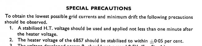
The Brimar 6BS7 is an audio tube which was built to a standard that allowed it to be used for Electrometer purposes.
The Brimar 6BS7 Data Sheet warns of mandatory pre-heating in electrometer applications (where low grid-current is supremely important).
Expressly, that the 6BS7 heater should be powered for 1 minute or more, before the HV arrives.
http://www.mif.pg.gda.pl/homepages/frank/sheets/019/6/6BS7.pdf
His suggested precautions against grid-current does offer an explanation for one other phenomenon, at least: the application environment for electrometer applications.
The Brimar 6BS7 is an audio tube which was built to a standard that allowed it to be used for Electrometer purposes.
The Brimar 6BS7 Data Sheet warns of mandatory pre-heating in electrometer applications (where low grid-current is supremely important).
Expressly, that the 6BS7 heater should be powered for 1 minute or more, before the HV arrives.
http://www.mif.pg.gda.pl/homepages/frank/sheets/019/6/6BS7.pdf
Attachments
- Home
- Amplifiers
- Tubes / Valves
- Tube amp high-voltage delay