Another Circlotron
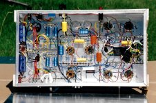
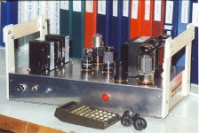
I did this one in 2001. 50W+ using 6550 or KT88s.
Its still sitting here on the shelf with several other of my brain storms doing nothing. Lots of measurement data including some running 6L6GCs.
Did a couple of odd OPT hookups, I'll post those later.")
I did this one in 2001. 50W+ using 6550 or KT88s.
Its still sitting here on the shelf with several other of my brain storms doing nothing. Lots of measurement data including some running 6L6GCs.
Did a couple of odd OPT hookups, I'll post those later.
Attachments

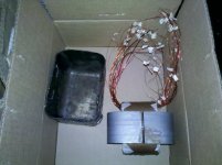
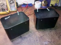
Here are some photos of when I wound McIntosh 75 OT's... I have wound these many times over the last 25 years...and they perform perfectly... Transformer engineering is my career no just a hobby...
Thought these photos would be interesting to see..
Thought these photos would be interesting to see..
Attachments
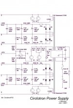
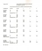
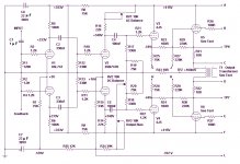
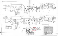
Rather than putting together a new explanation of the OPTs, Etc, I’ve simply copied parts of the original text of the article covering this amplifier. It was published in May 2002 issue of AudioXpress magazine.
DC resistance for the H125E’s was done by the 4-terminal method, driven by a SS CC source.
I don’t have any DC wdg Rs for the H300767 Hammond made for me. It is wound on the same core as an H1650N OPT. The primary is tapped similar to an UL, but set to reflect 1400R from the outer connexions or 800R from the inner pair. That way I could run PP 6550s or PP 6L6GCs. When the weather gets bad I’ll get some DC wdg Rs.
With the exception of the OPT there are no special parts or tube selection. All off the shelf.
Attachments
Here are some photos of when I wound McIntosh 75 OT's... I have wound these many times over the last 25 years...and they perform perfectly... Transformer engineering is my career no just a hobby...
Thought these photos would be interesting to see..
Wow, those are impressive. Thanks for posting the pic. Is every tag a separate external connection?
MC240, I have this information for you:
I think if you keep thinking about copying the McIntosn amplifiers, it’s good to know that you’ve already been ahead of yourself.
I have heard the MC275 and I can assure you that I have not perceived audible differences between it and this PL Evo 300 model.
" It seems everybody is looking for better bass. Especially if they are replacing a tube amp that has no slam, or bass that has poor definition. So they make the mistake of buying more power. Unfortunately, power means nothing when it comes to sound quality, dynamics, and bass slam. An amp can have 200 watts per channel, but if it doesn’t have output transformers with enough bandwidth, the speakers won’t receive it. PrimaLuna is one of only a few manufacturers in the world that actually designs and winds our power and output transformers in-house."
Why PrimaLuna? — PrimaLuna USA
PrimaLuna Evo 300 Tube Integrated — PrimaLuna USA
Rather than putting together a new explanation of the OPTs, Etc, I’ve simply copied parts of the original text of the article covering this amplifier. It was published in May 2002 issue of AudioXpress magazine.
DC resistance for the H125E’s was done by the 4-terminal method, driven by a SS CC source.
I don’t have any DC wdg Rs for the H300767 Hammond made for me. It is wound on the same core as an H1650N OPT. The primary is tapped similar to an UL, but set to reflect 1400R from the outer connexions or 800R from the inner pair. That way I could run PP 6550s or PP 6L6GCs. When the weather gets bad I’ll get some DC wdg Rs.
With the exception of the OPT there are no special parts or tube selection. All off the shelf.
Hey, thanks. My UC transformers have a 6.4k:8 impedance ratio, so when one tube is cut off, the other is working into a 1.6k load, which is twice your 800R. That alone explains a good deal of the difference in DF. My UC amp has an open-loop DF of ~7.3 (1.1 Ohm measured Zout).
I'm wondering if the Hammond H300767 just has relatively high DCRs as well? I know that the Plitron transformer I used is a really low DCR design. Less than 80 Ohm total primary resistance and a 0.18 Ohm secondary.
Local feedback ratio should be the same for the circlotron or the UC circuit. Did you run the output tubes particularly lean? That could raise Zout a bit too.
Cerrem, with your permission:
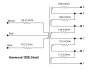
Hearinspace, you have to identify each winding, and also, I suppose it is also important to identify where it " comes in " and where it " comes out " . Once closed, you cannot do it by measuring resistance only.
Correct if I am wrong, the PDFs are very good but translating them is a pain, you have to copy, paste in the translator, etc.
Thanks anyway, jhstewart9
Last edited:
academia50,
jhstewart9 di mark the Phase of the windings in the drawing.
An oscillator and a 2 channel scope, are all that is needed to test the relative phase of any 2 windings (and all the windings).
It pays to do this kind of test, I have had commercial transformers that are marked wrong.
And that goes for Tweeters phase that is mis-marked too, but that is a more difficult test.
academia50,
jhstewart9 di mark the Phase of the windings in the drawing.
An oscillator and a 2 channel scope, are all that is needed to test the relative phase of any 2 windings (and all the windings).
It pays to do this kind of test, I have had commercial transformers that are marked wrong.
And that goes for Tweeters phase that is mis-marked too, but that is a more difficult test.
Another tactic is to put the windings in series.... The measure the AC voltage to see if it is adding or subtracting....this well tell you the phase relative to your reference winding...
Cerrem, with your permission:
Hearinspace, you have to identify each winding, and also, I suppose it is also important to identify where it " comes in " and where it " comes out " . Once closed, you cannot do it by measuring resistance only.
Correct if I am wrong, the PDFs are very good but translating them is a pain, you have to copy, paste in the translator, etc.
Thanks anyway, jhstewart9
Not sure what to make of this post, looks to be signed by me.
Response to two of us maybe?? Or three??
The PDFs I posted all opened for me on the forum, so I guess OK!!
Hammond provided the info I needed to get the primary connexions correct the first time. How cool is that!! And what we would expect anyway. Thru buz connexionz I knew several guys at Hammond, not far from where I live.
Just took a look at another H300767, new right out of the box. All eight primary leads & five secondary leads are brought out. So no problem with resistance measurements.
Just gotta make time to do that now.
All the several projects I did back then were strictly experimental. During my time as a sales & apps guy with HP & others I had been curious about some of the not so obvious toob amp circuits. This was one of those. The results were good, so I moved on. Except for a temporary hookup the amp was never set up to listen to at all. The amp was strictly a 'Proof of Concept' project.
academia50,
jhstewart9 di mark the Phase of the windings in the drawing.
An oscillator and a 2 channel scope, are all that is needed to test the relative phase of any 2 windings (and all the windings).
It pays to do this kind of test, I have had commercial transformers that are marked wrong.
And that goes for Tweeters phase that is mis-marked too, but that is a more difficult test.
I have managed to see the movement (minimum, of course) of the cone in a tweeter with the method of the stack and observing with a magnifying glass ..... but some do not accuse any perceptible movement ....
If the ends of the windings are not marked to know in which direction the turns advance, is not the same as not knowing the phase?
The first valve amplifier I assembled was the classic one I attached here known as "Silco".
I remember that he had hum, and he changes (uselessly) the OPTs believing they were to blame ... but the manufacturer attached the leaflet with the wiring and all the colors of the cables.
In those years (1967) the solid state began to "make noise", so assemble the classic RCA of quasi-complementary symmetry. The idea was to copy the MC Intosh MA6100! So to make it less complex, I decided to build the power and the preamp separately. At that time around here there were people who made the transformers to order, and did a good job.
I ordered EI oriented grain sheets, the winding attached to the middle for the two sections of the RCA (+ and -) and a 110 volt branch for the preamplifier.
The amplifier still works perfectly, the pre could never finish it.
I would have to upload some photos in the corresponding thread ....
Here is something ...
Preamp MC Intosh MA-6100 (DIY)
Attachments
Not sure what to make of this post, looks to be signed by me.
Response to two of us maybe?? Or three??
The PDFs I posted all opened for me on the forum, so I guess OK!!
I addressed all three, I'm sorry if it wasn't clear ......
I must not save post, obviously ...
academia50,
jhstewart9 di mark the Phase of the windings in the drawing.
I didn't see that .... I'm retired from these leagues and some things are missing me, I'm sorry
Another tactic is to put the windings in series.... The measure the AC voltage to see if it is adding or subtracting....this well tell you the phase relative to your reference winding...
Good advice, your OPT look great, sorry for intruding me, I just wanted to participate a little and alert (if not a troll) to MC240 ....
Realistic Audio Engineering- Crowhurst
Norman Crowhurst on UC. Audio Magazine Oct 1959
Norman Crowhurst on UC. Audio Magazine Oct 1959
Attachments
-
Realistic Audio Engineering Philosophy p1.pdf765.6 KB · Views: 171
-
Realistic Audio Engineering Philosophy p2.pdf835.7 KB · Views: 109
-
Realistic Audio Engineering Philosophy p3.pdf862 KB · Views: 101
-
Realistic Audio Engineering Philosophy p4.pdf758.3 KB · Views: 114
-
Realistic Audio Engineering Philosophy p5.pdf804.4 KB · Views: 102
-
Realistic Audio Engineering Philosophy p6.pdf608.5 KB · Views: 117
note:
I think the MC3500 was running with 475V B+, efficiency will be a little lower at 450V B+ here. The MAC was probably using around 260 Ohm Zpri (one side) (4 x 260 = 1040 Ohm P to P ) [ R = 425V x 425V / (2 x 350W) = 258 Ohm ]
Also, the knee V for PL519 drops to around 50 V at the lower peak current used now. (450V -50V = 400V delta) Screen V can be lowered until peak current can just be reached, that will lower the knee V further and improve efficiency.
So let's see: R = 400V x 400V / (2 x 400W) = 200 Ohms.
So 200 Ohms looks better for Circlotron Zprimary with the 8 x PL519 at 450V B+, and 400 Watt output.
For 350 Watt output at 450V B+: R = 400V x 400V / (2 x 350W) = 228.6 Ohms
I'm quite sure that I've read in one of the threads concerning the MC-3500/MI-350 that it's OT transforms the load to an effective primary impedance of 600 ohms, i.e. (1) 2400 ohms per tube pair, i.e. (2) 150 ohms per cathode and plate winding.
Best regards!
I'm quite sure that I've read in one of the threads concerning the MC-3500/MI-350 that it's OT transforms the load to an effective primary impedance of 600 ohms, i.e. (1) 2400 ohms per tube pair, i.e. (2) 150 ohms per cathode and plate winding.
Yes, those numbers do sound familiar. Apparently the Mac can do much more than the rated 350 Watts for short intervals. Like 600 Watts from those #s, so 350 Watts must be a steady sine wave power spec.
Peak Watts = 1/2 x (475 -50) x (475 - 50) / 150 = 602 Watts for short intervals (close to max tube steady state Pdiss for class B)
So, allowing for the so called audio "Crest Factor", one can design the OT and B+ for almost twice the steady state Watts (at least). (George - Tubelab probably would give an even more generous allowance factor, depending on music type) The spec'd low freq. end of the OT may not fully support such a large surge rating however.
Well, then the OT for a Circlotron should allow for the same "Crest" factor at least also. From the MC-3500 150/258 = 0.58 factor for the primary Ohms below the allowed steady state calc. (from total tube Pdiss) Or, equivalently, just design for max tube dissipation in class B and then derate the avg power rating by 40% for reliability. (20% to 30% derating may be more typical)
Last edited:
- Status
- This old topic is closed. If you want to reopen this topic, contact a moderator using the "Report Post" button.
- Home
- Amplifiers
- Tubes / Valves
- DIY McIntosh Amp