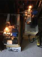
Hey, two woody amps featuring the 13em7 in a row")
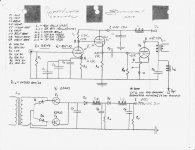
The diode isolation, as I understand it, prevents the drawing upon the previous section when demands of the tube exceed what was just presented. It’s something out of the RCA manual that a friend suggested. He said it allows the tubes to be fed only by the last LC and all the others are silent supporters. It’s a very low DCR supply. I can tell you the amp is hugely dynamic! I’d call it a 300B slayer!
The diode isolation, as I understand it, prevents the drawing upon the previous section when demands of the tube exceed what was just presented. It’s something out of the RCA manual that a friend suggested. He said it allows the tubes to be fed only by the last LC and all the others are silent supporters. It’s a very low DCR supply. I can tell you the amp is hugely dynamic! I’d call it a 300B slayer!
I think if you need those diodes in the B+ CLCLC filter, the reason is Very obscure.
I need someone to give a more definitive explanation.
When we have a power outage, the first cap will still have some charge, and the B+ will die gracefully with or without those diodes, right?
Anyway, a choke between two capacitors is not likely to see any really high frequency transients, if it does, the first cap is too small, take it out, and plan for a choke input supply, yes?
Of course also, do not use to large of a first cap, vacuum tube rectifiers do have their limits too.
There is a related thread on this site about power supplies for 811 tubes. I’m not sure how to link to it. I’m getting urged to change to an interstage transformer from the coupling cap but I know a fellow (SET12 from AudioKarma) who built this way (slight variation of one extra choke and the called for 2uF instead of the 1uF I could afford) and his amp ran strong and true for years. I’m betting on experience over theory... unless someone has differing Experience with A2 power supplies. I invite alteration to my schematic to reflect that experience. Experience is a great teacher, I’m all for it! Otherwise, This set up is a proven performer... with diodes and coupling cap . I’m not defending it in theory I’m just saying it works!
Cheers!
. I’m not defending it in theory I’m just saying it works!Cheers!
D1 and D2 are easily explained, and needed.
D3 and D4, nobody has successfully explained.
But perhaps D3 and D4 will make things a little better if the capacitors do not have enough capacitance, or if the inductors are not good enough.
I would be real interested to see the RCA article, and I would be willing to bet there were no inductors connected to the diodes, just resistors.
Last edited:
I will work on a drawing showing how to build an interstage into that design, since the cap coupled approximately zero biased output stage is far from ideal.
The two 100K bleeder resistors are going to live a short life dissipating that kind of heat. You can put the two of them in series across one of the caps to avoid this issue.
Those random diodes are something you could definitely do without.
The two 100K bleeder resistors are going to live a short life dissipating that kind of heat. You can put the two of them in series across one of the caps to avoid this issue.
Those random diodes are something you could definitely do without.
I still have 4 x 811-10a from when they were new to the market, plan was a pp amp. Things I think have moved on a long way from that design. I would definitely try them with a MOSFET buffer. I'm driving a pair of SE 833a with a simple powerdrive (c tubelab) circuit very successfully.
There is a related thread on this site about power supplies for 811 tubes. I’m not sure how to link to it. I’m getting urged to change to an interstage transformer from the coupling cap but I know a fellow (SET12 from AudioKarma) who built this way (slight variation of one extra choke and the called for 2uF instead of the 1uF I could afford) and his amp ran strong and true for years. I’m betting on experience over theory... unless someone has differing Experience with A2 power supplies. I invite alteration to my schematic to reflect that experience. Experience is a great teacher, I’m all for it! Otherwise, This set up is a proven performer... with diodes and coupling cap
Cheers!
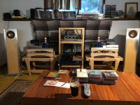
Beautiful amps, congratulations on your builds!
I modified a Tubelab TSE to run SV811-10 and it worked and measured quite good for an SE amp, particularly considering my mediocre Hammond 125ESE OPT's.
Personally, on my experience, I think the mosfet power drive is the way to go with these tubes. I was getting 9 watts with an inadequate positive power supply, and feel like 15 to 20 watts is within reach with the right one.
- Status
- This old topic is closed. If you want to reopen this topic, contact a moderator using the "Report Post" button.
- Home
- Amplifiers
- Tubes / Valves
- 811-10 mono blocks