Finally, tho' it does kind of make me a “KodaBMX shill”, I find a lot of attractiveness in his dual-toroidal-output transformer technique, and amplify-after-phase-inversion amplifier topology. Really straight forward, uses a LOT of output tubes if you have 'em to get quite high power. GNFB resolves most of the not-quite-audio-grade pentode 'knee' problems, too. Just saying,
GoatGuy ✓
...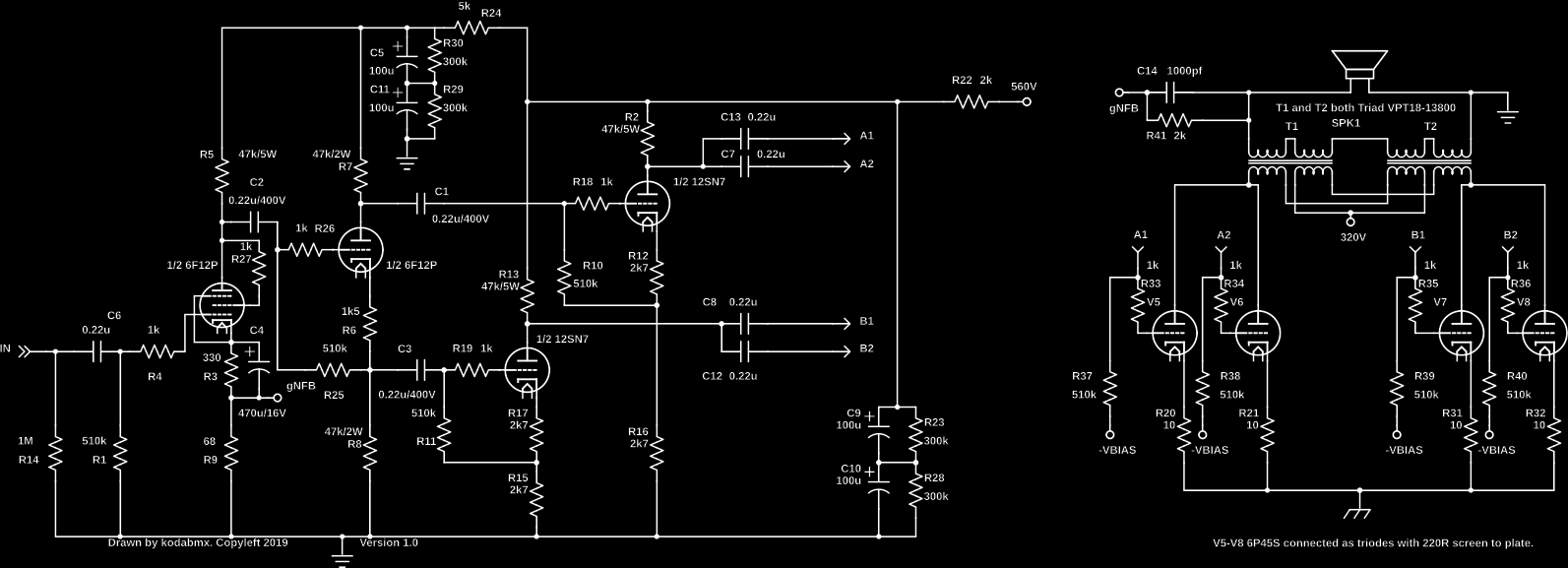
And there are no knee problems if you triode strap the output tubes as shown
") 112W@30Hz into 6R And once again a big thanks to Maxhifi for the idea for the wiring of the OPTs.
112W@30Hz into 6R And once again a big thanks to Maxhifi for the idea for the wiring of the OPTs.But why not? Paralleling the windings would reflect about 5k5:8R
Power transformers, especially toroids will often run into saturation problems when operated at high primary impedances due to the peak voltages across them.
These transformers were intended to run from 240 volts RMS at 50Hz. There is probably not much magnetic headroom above this.
Koda's design squeezes 112 watts through two of them. That puts about 382 volts RMS across the pair, or 191 volts RMS at 30 Hz each.
Running the same transformers at 5500 ohms needs 784 volts RMS across two or 392 volts each to get the same 112 watts. I'm guessing that saturation would seriously limit the maximum power output at low frequencies.
I have not tried Koda's unique wiring approach to toroidal power transformers used as OPT's. I just wired each pair of tubes to it's own OPT, then connected the output's in parallel..These were some dumpster toroids of a different ratio than what's shown here. I think they were 18 or 24 volt secondaries. Another possibility is the twin coupled approach, but I haven't tried it yet. The transformers are still in a box somewhere.
Actually, in my case since the load is only 6R the reflected load is about 1k. That means only 334V RMS across the pair. Of course you're right. Using a 5k5 load at the same voltage swing only makes 20W, so it's still good for an amp, just not 100W anymore. But on the bright side, you can use the 25VA coils and save $$$.
Also, I find these Triad transformers are good for more than their specs. It'll even make clean bass with one tube missing in push pull (100ma mismatch!) although not at full power obviously. In theory, this amp would make almost the same power with one pair missing, since they are rated for the current anyway.
Also, I find these Triad transformers are good for more than their specs. It'll even make clean bass with one tube missing in push pull (100ma mismatch!) although not at full power obviously. In theory, this amp would make almost the same power with one pair missing, since they are rated for the current anyway.
Last edited:
The ones I use are from a British company, Vigortronics, and although the primary inductance decreases to less than one half as the AC excitation is reduced, it is still a respectable 84H for the 50 VA ones at 1 Volt AC. They are also very modestly priced and work fantastically well with low impedance valves; my expensive Audio note Quests were given to my brother after my first build using these 10 years ago.
Good Sunday everyone,
I'm steering toward using 6LB6s and wanted to see what people thought screen voltage should be. Looking at the tube curves, GE has it at 110v. I experimented with these tubes some 8 years ago and don't remember what I used. Should I stick with 110 or should I inch it a bit higher.
Thanks
Ray....
I'm steering toward using 6LB6s and wanted to see what people thought screen voltage should be. Looking at the tube curves, GE has it at 110v. I experimented with these tubes some 8 years ago and don't remember what I used. Should I stick with 110 or should I inch it a bit higher.
Thanks
Ray....
I have never experimented with the 6LB6, so I can't say what the optimum voltage is. In audio amp service the screen grid voltage strongly influences the overall efficiency of the amp.
When playing with a tube I have never seen before, whether it's a sweep tube, or any other, I connect a variable power supply to the screen and try several different voltages taking the usual distortion, power output, and efficiency data. I will usually scope a control grid, and a low value resistor (1 or 10 ohm) in the cathode of one of the tubes.
The efficiency is computed by dividing the audio power output by the DC power fed into the output tubes. The audio power output must be measured under the same conditions each time. I use a standard 1KHz sine wave and crank up the drive until the amp reaches 3% THD.
If the screen voltage is too low the driver must push the control grid close to, or into the positive grid region. This will result in low power output, high distortion or clipping.
As the screen voltage is raised, the negative bias on the control grid must be increased to keep the idle cathode current constant. There often exists a pretty wide range where good power output and THD can be found.
If the screen voltage is too high the required negative bias is quite large to keep the idle current at the desired value. Often this gets into an area where the tube is nonlinear and THD increases, or the tube starts to exhibit bias drift.
Somewhere in that range where everything works good there will be a point or a range where the efficiency peaks, and drops off on either side. If you are squeezing the tubes for all they can give, this might be a single point. If you aren't beating them that hard, it could be a wide range. If so aim for the lowest THD in that range, or the lowest higher order harmonics if you have FFT capability.
For almost every sweep tube I have dealt with that was designed in the 60's or later, 150 volts has been close enough. Some of the early tubes needed a bit more voltage.
I'd triode strap it, run 120mA bias current and 300V B+. A pair with a 1k3 load should make almost 100W.
George has encountered runaway problems with big TV Sweeps over extended time in "triode" mode. Maybe check into George's latest "UnSet" approach.
------------------------------------------------------------------------------------------
Plot the load line on the tube graph for the P-P OT Zpri ( /4), with allowance for the idle current at zero signal, to find the Vscrn needed. Or use a variable power supply for the Vscrn initially to find the minimum needed for max output. Usually no more that 150V is needed for TV tubes. But you don't want excess Vscrn, or high screen currents will occur when over-driven.
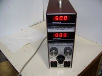
1) Hoefer PS 500XT 0-500V, 0-400 mA, 200 Watt, regulated, current limit, switching type supply (good for variable B+ supply) (recommend later model with fan on back)
Usually can get a good working one for around $100, don't see one right now.
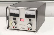
2) Hoefer PS 500 0-500V, 0-200 mA, 100 Watt, regulated, current limit, linear type supply (good for variable screen supply, fast limiting)
$19
Hoefer scientific PS 500 power supply, works as seen needs cord | eBay
Attachments
Last edited:
Good Monday everyone,
As always, thank you everyone for your inputs. Hopefully when this project is over I'll have something that is truly outstanding.
When it comes to high voltage delay, my intention is to have an Amperite Time Delay Relay control another relay. The "other" relay is a 3PDT relay. Besides delaying Plate and Screen voltage, would you delay Bias voltage?
The Amperite relay I have on hand is a 180 second unit. I'm thinking 180 seconds is more than enough time for the filaments.
Thanks as usual!
Ray
Those high value Amperite relays bounce at the sign of current draw and arc. If you mist use one, I'd use it to drive a transistor that controls an electromechanical relay.
As MelB said, connect the bias voltage on power up (switch it on with the heaters, and use a LARGE cap (220uF or higher I usually use) for it so when power is removed, the bias voltage will last longer than the B+.
As MelB said, connect the bias voltage on power up (switch it on with the heaters, and use a LARGE cap (220uF or higher I usually use) for it so when power is removed, the bias voltage will last longer than the B+.
Thank you all for the hints on the Amperite. I had the Tine Delay Relay and the 3PDT relay sitting around, so I thought I would try them. I know there are solid state units out.
The Amperite is a 6 volt model as is the relay, so hopefully the Amperite doesn't take a beating. The 3PDT relay is rated for 1500 v between contacts, I have a spare just in case....
The Amperite is a 6 volt model as is the relay, so hopefully the Amperite doesn't take a beating. The 3PDT relay is rated for 1500 v between contacts, I have a spare just in case....
That might be wise, breaking DC at significant voltage is hard, if there's enough power to sustain an arc you can start fires inside a switch. A snubber will allow the voltage across the contacts to stay low until they have separated to sufficient distance. Best is to use contacts rated for the voltage and current involved.
- Status
- This old topic is closed. If you want to reopen this topic, contact a moderator using the "Report Post" button.
- Home
- Amplifiers
- Tubes / Valves
- Possibility of 100 Watts?