Can you scope where it originates? Is it already at the input, driver output, output stage only? Do some diagnosis?
Where is the scope gnd clip connected to?
Because one channel is good, is there an obvious difference between channels in grounding, or ground wiring?
Is the input connector ground from both inputs connected to a ground somewhere? Have you tried to disconnect one of the input connector grounds to open the ground loop?
Also, what you show on the scope is typical power supply ground, so it is not from mains ground or mains earth. Typical this occurs when a power supply ground run is also used by a signal input ground run or speaker return ground run. If you scope with scope ground clip to input RCA ground, and the scope probe to the chassis ground, are you also seeing it then?
Jan
So what were the results of these tests?
These questions are designed to locate the origin of the issue. Going through them one by one will give the rest of us clues instead having to trial and error.
Jan
Probably a leak heater-cathode in B1b.
You could put an capacitor over R7 (100µF-10V), but P3 has to be re-adjusted.
Mona
Having switched tube from left to right for test, it can't be the tube. I scope that R7 and it's silent, no noise there.
Replying :So what were the results of these tests?
These questions are designed to locate the origin of the issue. Going through them one by one will give the rest of us clues instead having to trial and error.
Jan
Can you scope where it originates?
Is it already at the input, driver output, output stage only? (Actually it's on the speaker output. I could not find any other humm (60 hertz) anywhere on the circuit. I checked on the grid input of every tube - none. The only spot I didn't probe was the plate of the output tube EL34 (B2-B3), which in my build are KT77...))
Where is the scope gnd clip connected to? (Case ground)
Because one channel is good, is there an obvious difference between channels in grounding, or ground wiring? (Not that I see... being built on a PC board designed by VanderVeen, I doubt there could be a problem into it.)
Is the input connector ground from both inputs connected to a ground somewhere? (Yes. But as the volume pot is down. Raising it, same difference)
Have you tried to disconnect one of the input connector grounds to open the ground loop? (yes)
Also, what you show on the scope is typical power supply ground, so it is not from mains ground or mains earth. Typical this occurs when a power supply ground run is also used by a signal input ground run or speaker return ground run (my guess too...those are very difficult to catch)
If you scope with scope ground clip to input RCA ground, and the scope probe to the chassis ground, are you also seeing it then? (curiously, yes but very little, if it was there, it should appears along across the circuit being amplified here and there, isn't ? and if that's true, why is the right channel so silent ? I guess a ground loop should be present on both channel ?
Two channels are not always exactly the same so there is always a difference, but not as much as you see.
The fact that you see hum between the input and chassis ground points to some ground loop.
If the RCA input ground is grounded directly at the input, try to run that ground to the chassis at some other point, where you scoped that hum. See if that makes a difference.
I know Mr. Vanderveen, I'll ask if he has an idea.
Jan
Thanks
I’ll try.
Thanks.
I already texted to mister Vanderveen. As I didn’t buy the unavailable kit, I just bought the pc board and found the parts by myself, he was not so pleased. So I would not bother him with that, if you don’t mind.
I don’t think any of my parts to be different from the original design since I have 20 years + in electronics and I know my way around.
Like I said, ground loop is always a bitch to catch ;-)
I had the same problem with transistor amps I built but it was easy to find.
I have no experience in tube amp and trouble shouting is a bit more dangerous so that’s why I search for advices.
Again, I thank you for your very appreciated and accurate help !
Rather confusing.
Post 18 i proposed to exchange the tubes right/left to see if it makes a difference.
Post 19 : yes it does
Post 23 : it makes no difference ???
If you find no hum inside the amp but only out of the output transformer it can be the magnetic field of the supply transformer (or a choke). The hum could come from bad orientation of the transformers.
Mona
clarification
Post 18 i proposed to exchange the tubes right/left to see if it makes a difference.
Post 19 : yes it does
Post 23 : it makes no difference ???
(I was replying to another guy. I did the tube switch from left to right, ans NO it doesn't make any difference. Hence, tubes are OK.)
If you find no hum inside the amp but only out of the output transformer it can be the magnetic field of the supply transformer (or a choke). The hum could come from bad orientation of the transformers.
(that was my last resort idea... that I fear cause to displace or replace is a major task. That's why I was looking everywhere else before).
Sorry for the confusion. I will switch around grounds to see it it makes any difference.
Thanks, really.
Tip from Mr. Vanderveen: check if both output tubes draw the same current without signal (measure voltage across cathode R). Unequal current can cause hum. If the currents are not equal, adjust for equal current.
If you can't adjust, one power tube is probably shot.
Jan
That's well documented into the assembly manual. I did. No diff.
But right channel draw 61 as left draw 63. Could not be a problem.
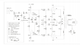
As voltage, the schematic says 125 volts. I measure 85. I was thinking about changing R5 - R8 to 39K so raising the voltage closer to 125 volts.
But I was trying to correct the ground loop problem first.
Serge
Looking at the data, the 125 volts on the anode with a cathode resistor=680Ω is more ore less right for a 6N1P from Svetlana.As voltage, the schematic says 125 volts. I measure 85. I was thinking about changing R5 - R8 to 39K so raising the voltage closer to 125 volts.
To get the same anode voltage with an regular 6N1P you need an Rk ~1k and with the ECC88 ~1k2.
All cases with 3mA anode current, not very much for those tube.
Adjusting Ra to get Va=125V seems a good idea, it results in more Ia = more linear region.
Mona
Current confusion
Here it goes.
The anode voltage of 85 volts is from the anode of B1a B1b (in that case, I use ECC88), that I plan to reajust to be near 125 volts.
As for the measure of current, I was talking of setting the quiescent current of B2-B3, I use KT77 in place of the EL34 in the schematic 59 Ma I get around 67 Ma.
Last, are you saying just changing R5-R8, not touching R6-R7 (I think the current of K is OK as you said.
Thanks
Talking to 2 persons can lead to confusion. My fault. I was not clear enough.But he says he has 62mA Ik ...
Jan
Here it goes.
The anode voltage of 85 volts is from the anode of B1a B1b (in that case, I use ECC88), that I plan to reajust to be near 125 volts.
As for the measure of current, I was talking of setting the quiescent current of B2-B3, I use KT77 in place of the EL34 in the schematic 59 Ma I get around 67 Ma.
Last, are you saying just changing R5-R8, not touching R6-R7 (I think the current of K is OK as you said.
Thanks
Probably a leak heater-cathode in B1b.
You could put an capacitor over R7 (100µF-10V), but P3 has to be re-adjusted.
Mona
I did that. No change.
Back to square one....
Was to be expected since the exchange of the tubes didn't make a difference.I did that. No change.
Back to square one....
Mona
Back to rebuild
Being enable to find the source of the ground loop, I figure it could be generated by the output transformer itself. So I switch left to right. I took this opportunity to recheck all parts and traces, solders and possible shorts.
Long process but, hey, when the clue doesn’t manifest itself, one has to investigate.
I’ll rebuild it and see if that ghost humm is still there. If so, something is wrong with that board.
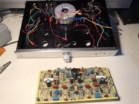
Attachments
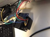
ul40-s2 vander veen amp ground loop and setting
This amp has been a challenge so far as built it with some change to improve the sound quality. So I was not sure if the problem of ground loop or similar ground problem caused by the output transformer I had was a bad part or the changes I made. After several nights of test and measure, flipping the transformer around, and communication with the Chinese supplier (I didn't buy the toroid transformers, which are way too expensive), I finally found that one transformer was bad. Further tests proved that the color coding of the input wires were crossed on 2 of them, from plate to control grid, and of course, rendering the poor output tube mad !
When I changed that, everything went ok, but some 100Khz oscillation I couldn't find the source. After several tests, I found the ground coming back to the output at R25 was the source ! Disconnect it and now the amp is quite silent !
Here are other changes :
EL34 replaced by KT-77
6922 replaced by E88CC
Now, according to schematic, I should have 125 volts at the plate of B1-a / B1b, but no. I changed R5-R8 to 39K, and I now have 88 volts. I plan to lower it further but I think I also make R6-R7 to 1k or 1.5K.
What do you think ?
Attachments
- Status
- This old topic is closed. If you want to reopen this topic, contact a moderator using the "Report Post" button.
- Home
- Amplifiers
- Tubes / Valves
- UL40-S2 Van der Veen amp problem