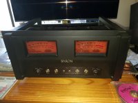
I have to replace a few bad caps and burnt resistors on my newly acquired Mesa Baron amp. My experience up to now has been SS only. Looking for guidance from someone here that may have done work on one. First question is how to I get access to audio circuit board with tube sockets on it to replace needed parts?
Attachments
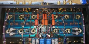
Looks brutal, with lots of wiring in the way, and sockets both bolted to the chassis and soldered to the board. Seems like you would have to unsolder all the tube sockets to release the board. You could try to replace the resistors from the visible side without removing the board, unless you are doing a complete refresh of most of the components. It's clearly not designed for ease of servicing, to put it mildly.
Last edited:
Like Ray says it's brutal, but parts replacement is possible. It's just a lot more tedious then normal. Removing the board is not necessary. The problem parts are the radial capacitors which will need to be destroyed to remove while leaving the leads intact. The resistors and axial capacitors, not so bad. By using a proper soldering station (like a Weller WTCPN for example) with a pointed tip, heat the part lead and lift each end up and out of the board one at a time. Then use a solder sucking iron to remove the solder from the hole. A desoldering wick will work, however it takes a bit of expertise and practice to use that well without damaging the board.
Alternatively by cutting the component's lead close to the body leaving a piece in the board and then grabbing that with a small precision long nose pliers while unsoldering it. Then solder suck the remaining solder off. A good video to watch about removing components from circuit boards is this one from Mr. Carolson's Lab. (I hate how he pronounces the "L" in solder.)
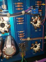
Installing a replacement radial capacitor is tricky without removing the board. Hopefully there is a plated through hole for these. Otherwise try leaving the leads stuck in place and soldering onto them. You may have to angle the capacitor somewhat.
Alternatively by cutting the component's lead close to the body leaving a piece in the board and then grabbing that with a small precision long nose pliers while unsoldering it. Then solder suck the remaining solder off. A good video to watch about removing components from circuit boards is this one from Mr. Carolson's Lab. (I hate how he pronounces the "L" in solder.)
Installing a replacement radial capacitor is tricky without removing the board. Hopefully there is a plated through hole for these. Otherwise try leaving the leads stuck in place and soldering onto them. You may have to angle the capacitor somewhat.
Are you sure if this is absolutely necessary? Could you supply a close-up of the damaged components?I have to replace a few bad caps and burnt resistors on my newly acquired Mesa Baron amp.
yes, that is the way I would do it. With plated holes there is a good chance to replace parts without removing the pcb.
First I would leave the old leads and solder the new parts to those leads. Then if and when the unit works, you can try a more permanent installation, if you want. If the amp won't be carried around, you could consider just leaving it that way.
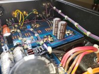
I actually have 2 of the amps. I was told that the 10k Sprague caps in pics need to be changed as they are known to be leaky. Also on one of the amps I noticed 3 resistors that must have overheated as they are charred. They are shown in pic. I would like to change out the orange drop caps too. I will move slow with this one for sure. Thanks to all
Attachments
Well if it does come down to removing the board I will have the other amp to use as a reference. rayma, you mentioned the sockets are bolted to the board. What exactly does that mean? While researching mods to this amp I came across this and that's where I got the idea of replacing the orange drops. Modified Mesa Baron with Audio Note PIO and SCR caps. Just looking for the best sonic improvements and of course replacing the problem parts.
Attachments
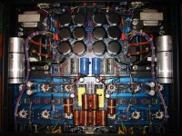
It appears that the sockets are bolted to the chassis, and then the board is dropped over the sockets,
and the socket lugs are soldered directly to the board. This means all the lugs on all the sockets would
have to be desoldered to remove the board, a very nasty job. Maybe someone can confirm this.
and the socket lugs are soldered directly to the board. This means all the lugs on all the sockets would
have to be desoldered to remove the board, a very nasty job. Maybe someone can confirm this.
Also, what could have caused the 3 resistors to overheat?
Well, that implies there are more problems. I would repair before changing working parts.
Maybe you'll like it just fine without changing any working parts.
Last edited:
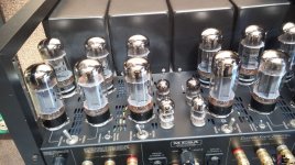
Each channel uses six output tubes in PP parallel. The burnt resistors I see are one group of several similar groups. An educated guess is they are used with the output tubes, probably grid, screen and/or plate "stopper" resistors. One of the power tubes is a very likely culprit having gone bad and taking the resistors with it.Also, what could have caused the 3 resistors to overheat?
The radial capacitors on the power supply board would require the boards removal. But the 10K radials on the amplifier board are small enough in diameter that a large pair of side cutters could cut them near the bottom of their body just above the board. Perhaps not in one bite, but two or three will do the job. But make very sure they really do need replacing.
And it's a crying shame that the morons that designed the layout and mechanics of that amp used every shortcut available to cut the manufacturing cost at the expense of servicing. Like no connectors for the wiring. And it appears that the tube sockets really are bolted to the chassis instead of just being soldered to the board, and the board supported with stand-offs throughout it's length and width.
Attachments
A servicing nightmare; there´s no other way to call it.
Just checked online pictures and sockets are bolted to the chassis, from the *outside*
For a couple extra dollars they might have attached nuts to sockets so they could be mounted on the inside of the chassis, so external bolts go trough holes and removing them allows you to remove PCB with sockets still soldered to it.
As is, it´s madness.
- Status
- This old topic is closed. If you want to reopen this topic, contact a moderator using the "Report Post" button.
- Home
- Amplifiers
- Tubes / Valves
- Mesa Boogie Baron tube amp