Hello to all,
My brother wants to build a tube phono stage. While he solders well, he is inexperienced with tubes so (as he doesn't have an acc here) he asked me to open a thread and gather some info.
What he needs is a one stage tube amplification with the highest possible audio quality. The RIAA circuit will be tested according to his thought later and according to the amplification stage.
For requirements he has the following:
1) 3mv-->300+mv with one stage only (the more mv the better ofc)
2) Balanced implementation is a strong plus
3) Lowest possible noise/highest linearity
4) Lowest possible PSU voltages (<24v if possible? i don't know)
5) Any tube or material recommendation.
Our budget is 100-120 euro. This is only for the parts. It excludes board and PSU materials. Can stretch by a margin if it brings some serious/good/easily heard better sound.
Please when you state your opinion give also the reasoning behind it.
Changes can be made in our thinking if for example you tell me that a 265v high voltage beats hands down ANY 60v (or any other voltage) implementation, we will go for the higher voltage anyway against our will (which in this case is up to 24v).
I would also like to know which EU sources for materials you choose and why. Especially for tubes but also for all other materials.
I would like to thank everyone no matter how small his contribution is, in advance. I'm grateful for the time and effort you put in this thread and in general on this forum.
")
Regards,
Tas
My brother wants to build a tube phono stage. While he solders well, he is inexperienced with tubes so (as he doesn't have an acc here) he asked me to open a thread and gather some info.
What he needs is a one stage tube amplification with the highest possible audio quality. The RIAA circuit will be tested according to his thought later and according to the amplification stage.
For requirements he has the following:
1) 3mv-->300+mv with one stage only (the more mv the better ofc)
2) Balanced implementation is a strong plus
3) Lowest possible noise/highest linearity
4) Lowest possible PSU voltages (<24v if possible? i don't know)
5) Any tube or material recommendation.
Our budget is 100-120 euro. This is only for the parts. It excludes board and PSU materials. Can stretch by a margin if it brings some serious/good/easily heard better sound.
Please when you state your opinion give also the reasoning behind it.
Changes can be made in our thinking if for example you tell me that a 265v high voltage beats hands down ANY 60v (or any other voltage) implementation, we will go for the higher voltage anyway against our will (which in this case is up to 24v).
I would also like to know which EU sources for materials you choose and why. Especially for tubes but also for all other materials.
I would like to thank everyone no matter how small his contribution is, in advance. I'm grateful for the time and effort you put in this thread and in general on this forum.
Regards,
Tas
Linearity, for the most part, is going to be inversely proportional to your voltage. The lower your voltage the worse it gets.
Asking for 100:1 from a single tube stage is asking a lot. Might be able to get away with a 100V B+ using a CCS loaded 12AX7. Should be linear enough with 0.8-1mA on it. This would give you one tube for single ended amplification and two for balanced, minimum, and doesn't take into account the losses of your RIAA filter which will eat into your gain quite a bit.
But if I can be frank with you, it's next to impossible to get what you want with a single tube element per channel. If it were possible to use a single tube element for huge, linear gain with less than 24V everybody would use it.
You should be able to build just about any RIAA amp out there with 100 euro since most of them use either the 6DJ8 or 12AX7 which can be had for plenty cheap even if you need 4 of them.
I understand your point. If 24v is not a viable option, then it goes away.
We will stay as low as possible, but not the point where we are going to start losing quality.
With 2 tubes/channel for balanced configuration, is there something you would like to point out?
Also for the tubes, i understand that 6DJ8 or 12AX7 are popular and cheap. But as far as audio quality is concerned, are these the best choices? And if they are, all (e.g) 6DJ8 sound the same or there is a definite upscale in quality from some brands versus others?
thank you very much
Note also that a passive or a feedback type phono equalization will yield -20 dB amplification referred to the open loop gain.
You mean from the riaa correction.
I think my brother has considered this into account.
But still thx for pointing out. We might lose any detail due to lack of experience.
thx a lot!Since you don't say something, i presume that it is close to what i asked.
What is the effect of the passive components quality wise?
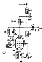
the tube is EF86 i see and this is one channel right?
Building a 24V supply or a 240V supply isn't any different from each other. Voltage ratings of parts chosen need to be different but that's still easy territory.I understand your point. If 24v is not a viable option, then it goes away.
We will stay as low as possible, but not the point where we are going to start losing quality.
With 2 tubes/channel for balanced configuration, is there something you would like to point out?
Also for the tubes, i understand that 6DJ8 or 12AX7 are popular and cheap. But as far as audio quality is concerned, are these the best choices? And if they are, all (e.g) 6DJ8 sound the same or there is a definite upscale in quality from some brands versus others?
thank you very much
Brands of valves chosen don't matter.
For a balanced circuit having about the same behaviour for the positive and negative side is a nice feature, easiest obtained with a seperate valve for each. Using one side of a double triode for each part of the signal will result in some offset. If you can do your own matching get 10 (current make like Electro Harmonix or whatever) 12AX7, parallel the halves and find your pairs.
You can get as expensive and exotic in tubes as you want. I don't personally hear a difference between my RIAA equipped with cheap Russian 6N2P tubes or swapped out to a pair of expensive 12DF7s. Sure the DF7s take banging on the table better but that's not the norm for this amplifier.
But, this conversation can open a huge can of worms so...
About balanced operation, if you stay balanced for input and output you will need 4 RIAA circuits as opposed to only 2 for regular stereo. I'm building a balanced input, single ended output RIAA amp soon and it does the balanced to single ended conversion before getting to the RIAA correction for this reason.
**edit** Damn, I forgot about pentodes!
Nice. Pentode input is the way to go for phono. How about an E810F instead of the EF86
You can get as expensive and exotic in tubes as you want. I don't personally hear a difference between my RIAA equipped with cheap Russian 6N2P tubes or swapped out to a pair of expensive 12DF7s. Sure the DF7s take banging on the table better but that's not the norm for this amplifier.
But, this conversation can open a huge can of worms so...
About balanced operation, if you stay balanced for input and output you will need 4 RIAA circuits as opposed to only 2 for regular stereo. I'm building a balanced input, single ended output RIAA amp soon and it does the balanced to single ended conversion before getting to the RIAA correction for this reason.
**edit** Damn, I forgot about pentodes!
you are right and thx for pointing out. i don't want to open such a can....
I only asked because i have lived with QUADs and maggies almost half my life. All my systems could show small differences and i am used to this. This is the reason i asked. I understand you are seasoned in electronics. I do not know your system specs but since you have spend money on this hobby (from changing tubes alone
)i also assume that you have a "hi-end" system which shows the differences and again, i assume you are an experienced listener. If my assumptions are correct, i should trust your opinion as i don't ask for a different "taste" or small differences (indeed to many people small differences may be significant) but rather i'm looking for the context. And your answer i think is sending me to the right direction. If i want later i might swap tubes or do whatever experimentation. For now i will stick to your advices. thx again for this detail!
Building a 24V supply or a 240V supply isn't any different from each other. Voltage ratings of parts chosen need to be different but that's still easy territory.
Brands of valves chosen don't matter.
For a balanced circuit having about the same behaviour for the positive and negative side is a nice feature, easiest obtained with a seperate valve for each. Using one side of a double triode for each part of the signal will result in some offset. If you can do your own matching get 10 (current make like Electro Harmonix or whatever) 12AX7, parallel the halves and find your pairs.
i will follow your advice. tyvm sir!!!
It's the input stage of an old Philips amp from ~1951. The E810F is a competely different tube not made for audio. It could function with the older allmost identical EF40.Nice. Pentode input is the way to go for phono. How about an E810F instead of the EF86
Mona
This may be hugely unwelcome, but I find it odd that the driving goal(s) for the phono preamplifier specifically require all-gain-in-one-stage and no RIAA compensation network. Its like the cart is pulling the horses.
To me it is perfectly laudable to have overall preamp criteria of … +40 dB gain before RIAA compensation, to have –70 dB harmonic distortion, to amplify a nominal 3 mV signal from the moving magnet phono pickups. All quite normal. I say “let those drive the design”, unless some theory-of-why-not can be floated and justified.
in this example, I would much rather have 2 gain stages than one. Degenerating the cathode of the first and second by not using capacitor-bypassing on the cathode resistors for super-local negative feedback (for me) is a given. 2 stages also makes the unavoidable (and some would say, “cherished”) vacuum tube nonlinearity far more symmetric, suppressing the wolf harmonics substantially.
This also allows for an asymmetric gain-stage approach: +28 dB (25×) gain S₁ first stage, +12 dB (4×) for the S₂ second stage, with S₂ having a more robust RA anode resistor delivering much lower output impedance than S1. With our friendly dual-triodes, its “all in one envelope” too. Close-close wiring on the socket to suppress parasitics, RF and all that.
Anyway, I offer my apologies if this is too heretical an approach for solving the OP's part-design-goal, part-caprice-goal effort.
Just saying,
GoatGuy ✓
I don't think has a touched on a major flaw yet, at least not directly. I think the OP is assuming that the 1st gain stage and a subsequent RIAA stage can be treated as separate design blocks. They cannot be because the RIAA block is in parallel with the gain stage. The RIAA block values will change depending on the gain stage. This is the major flaw; no point saying "yeah, yeah, we get this" because you do not seem to get it.
…because the RIAA block is in parallel with the gain stage. The RIAA block values will change depending on the gain stage. [this is a major design consideration, not to be lightly set aside]
Just as a point of order, I don't think characterizing all RIAA blocks to be in parallel with gain stages to be accurate.
They can be entirely passive-and-in-series with a sufficiently robust signal of critically low impedance. I believe further that combining the RIAA network within the phono preamp is nearly universally embraced because of the quixotic nature of 'designed as separate stages' issues.
Tho' harder to calculate with precision (and find components of actual value, not theoretical value), combining all into one phono stage expressed as
S1 +28 dB
→ S2 +20 dB
→→ RIAA network –20 dB
→→→ S3 +16 dB
→→→→ S4 +0 dB 'cathode follower' buffer
makes an awful lot of good sense. → S2 +20 dB
→→ RIAA network –20 dB
→→→ S3 +16 dB
→→→→ S4 +0 dB 'cathode follower' buffer
You'll have a 0 dBu (775 mVRMS nominal) signal to feed to the rest of your brother's system. And the whole amplification path can be quite linearized thru degenerate cathode resistor biasing (i.e. no bypass caps) throughout.
Just saying,
GoatGuy ✓
Mona's suggestion of a pentode is definitely the way to go, if all the gain is to be lumped into a single stage. While the EF86 is an excellent tube, its S/N performance will be marginal in this application. Superior S/N performance is associated with high transconductance (gm). The EF86 is a low gm type. I suggest the 6AC7 pentode, with its high gm.
In addition to satisfactory S/N performance, linearity is a factor of major importance. Linearity of pentodes is maximized by regulating screen grid (g2) B+.
Gain will be maximized by isolating the pentode from the following RIAA EQ network. Read "MOSFET Follies" and DC couple IRFBC20 source followers to the 6AC7 plates.
As an intelligent fellow named Einstein indicated, simple is good, but not so simple that correct operation is precluded.
- Status
- This old topic is closed. If you want to reopen this topic, contact a moderator using the "Report Post" button.
- Home
- Amplifiers
- Tubes / Valves
- Tube phono stage w/no RIAA components